Writer’s Note: A few weeks ago we introduced the 3DR Iris+ drone upgrade project we were working on. This week, we’re diving into some of the modifications we had to make to the electrical system that make the upgrade with high strength 3D printed replacement parts possible. Follow along as our 3D printed carbon fiber drone becomes a reality!
Welcome back everyone to this installment of our 3D printed carbon fiber drone build log! This week, we’re going to focus on the non-3DP modifications that are required in order to make the 3DR Iris+ ready to accept 3D printed upgrades made on our Mark Two printer — specifically the four brushless motors that power the drone.
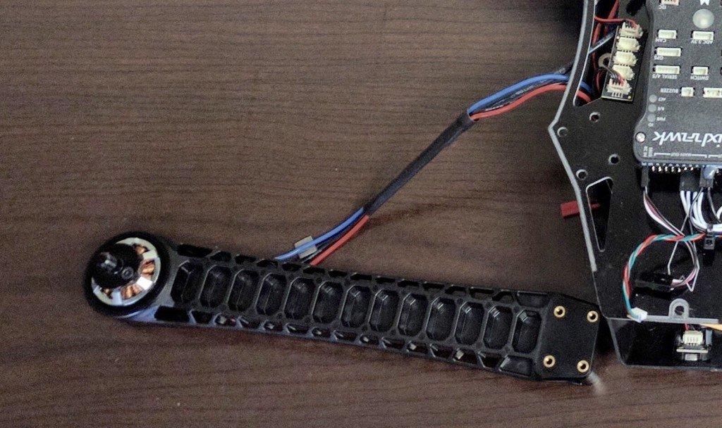
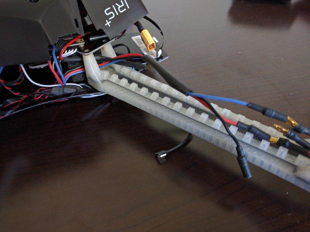
A frustrating realization — the brushless motor wires are threaded through the arm, and then soldered to the main board — time to break out the wire cutters!
While the Iris+ is an excellent platform for aftermarket upgrades, especially of the 3D printed variety, it wasn’t designed to be as modular as we’d now like it to be, and so I ran into some wiring issues. When I first began disassembling the drone, I was happy to discover that all the wires leading to the Pixhawk flight controller, which serves as the brains of the drone, were completely connectorized, and were easily removable. This early win was quickly undone however.
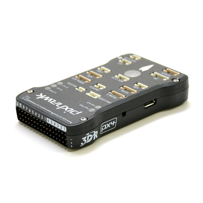
The Pixhawk flight controller at the heart of the Iris+ platform
Unfortunately, when I reached the electronic speed controller (ESC) and main power distribution board, which routes the correct amount of power to the brushless motors at the end of each arm of the drone, I found that the brushless motor leads were soldered directly to the board, after being routed through a small hole on the arms. In effect, this makes it impossible to remove the motor from the stock plastic arms without either destroying the arms, or cutting the motor leads.
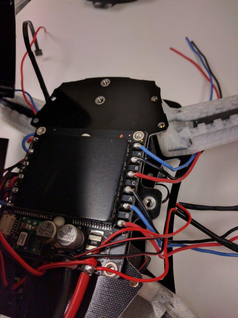
Good design for manufacture (DFM) conflicts with our goals — the motor leads are directly soldered to the board!
Since I had just purchased the drone, it felt wrong to wreak wanton and irreversible destruction on the arms, so I chose to cut the motor leads instead.
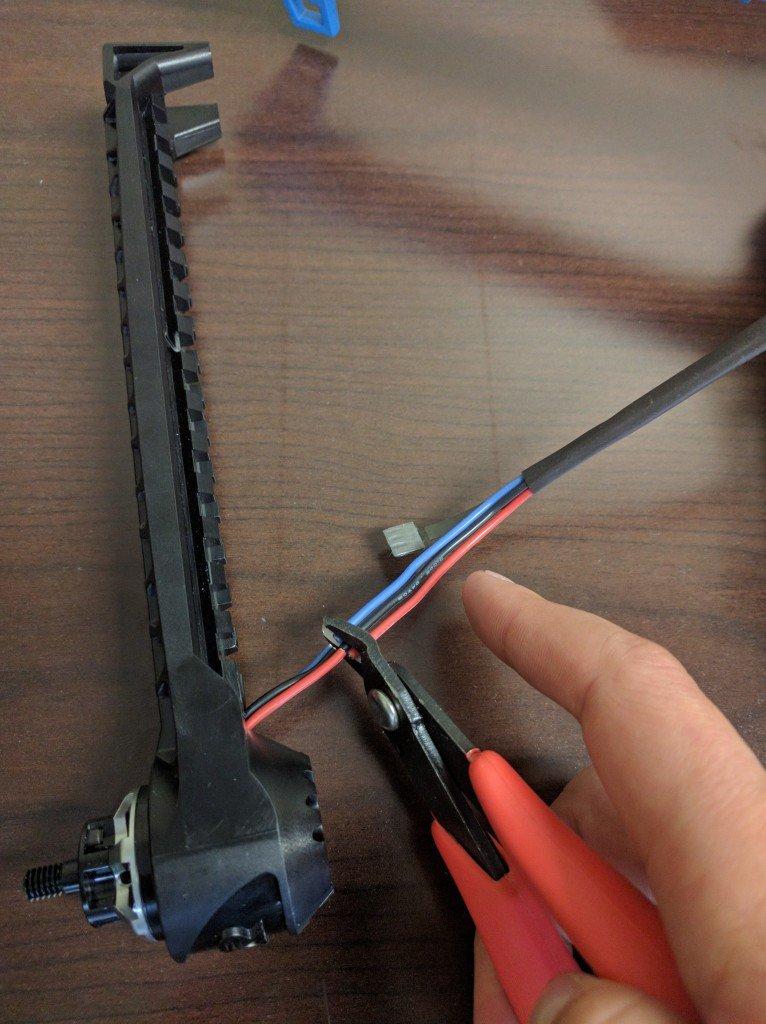
Cutting the motor leads between the motor and the LED strip on each arm— much easier to stomach!
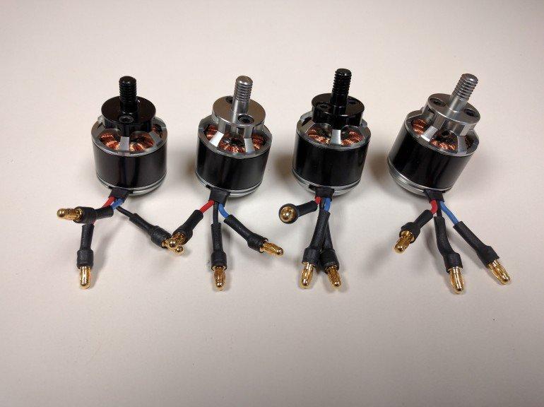
I didn’t want to re-solder all the motor leads back together once we had installed the motors on the new carbon fiber 3D printed arms, since we might want to upgrade them with additional designs down the road. So I decided to add miniature 3.5 mm banana plugs to all of the leads for ease of use down the road.
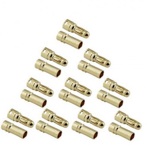
3.5 mm banana plugs, perfect for RC applications
I soldered the male connectors to all of the motor-side leads, and vice versa, and then added heat-shrink tubing to fully insulate all exposed conductive surfaces.
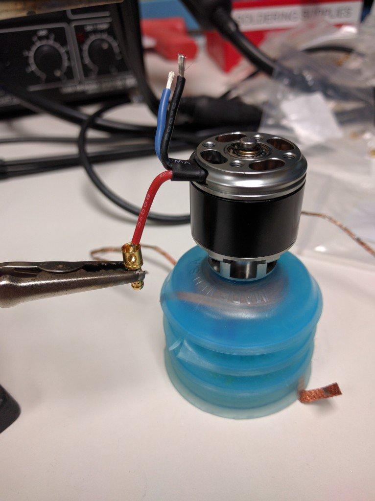
Soldering the banana plugs onto the motor leads
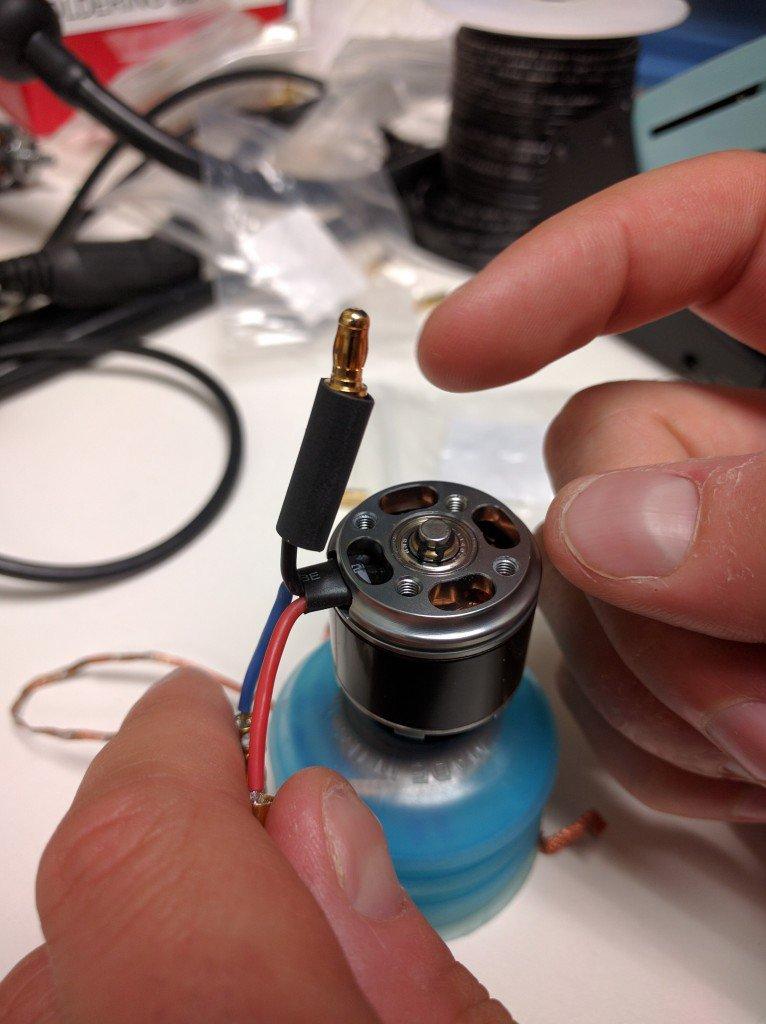
Adding heat-shrink insulation with my massive thumbs
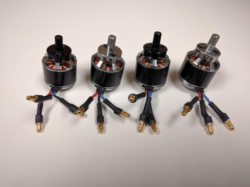
The final lineup!
Once all of the newly connectorized wires were completed, it was fairly simple to thread the new connectors through the 3D printed arm, enabling us to now upgrade the Iris+ at will!
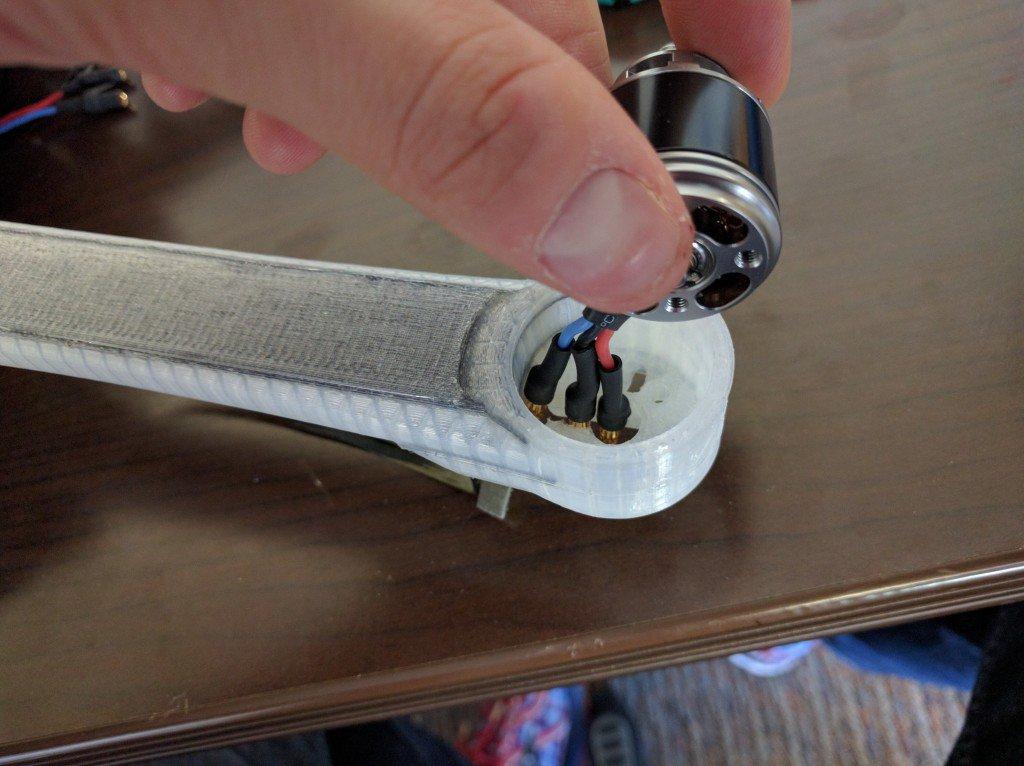
Threading the new leads through the bottom of the 3D printed arm
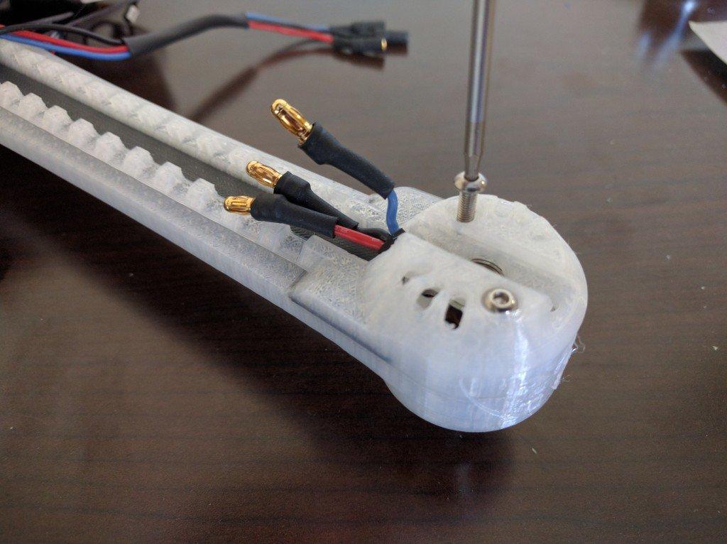
Final installation of the brushless motor into the arm
The rest of the arm
We’re almost ready to re-assemble the Iris+ and get it ready to fly! Check back with us soon in our final installment of this build log as we finish the drone up and take our first flight!
Want to see what you could do with industrial strength 3D printing? Check out a free a sample of parts printed on the Mark Two today!

