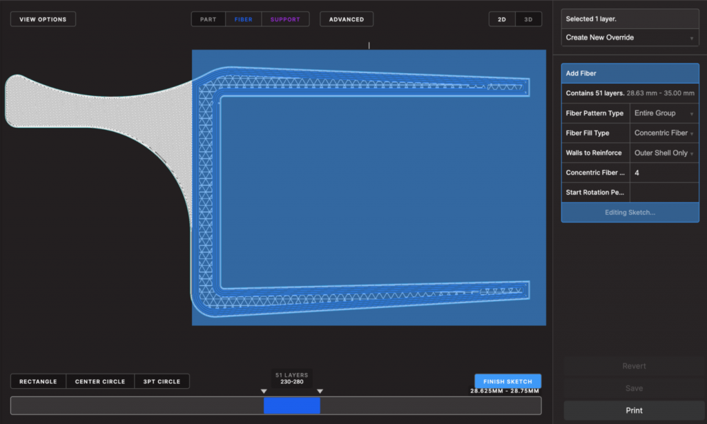
New fiber layout adjustment tools ensure cost-effective strength
Reinforcing 3D-printed parts with continuous fibers—such as glass or carbon fibers—is a valuable manufacturing capability. It allows users to easily print parts that are much stiffer and stronger than parts made solely of plastic. When adding fibers to a part, the user must make several decisions: the type of fiber fill (concentric or isotropic), the amount of fiber to use, and the location in the part where the fibers should be applied.
While the default fiber settings work well for many applications, certain scenarios require manual fiber placement. Fiber overrides provide more control over fiber placement and allow the user to customize fiber settings for specific layers.
In the past, these custom fiber override settings could only be applied to entire layers. In response, we're announcing a new feature—the Fiber Override Sketch—that allows users to control fiber placement within each layer.
Why override fiber sketching?
This new feature offers greater control over fiber placement. Users can selectively reinforce key features of their parts without reinforcing the entire part or layer. This enables more efficient use of continuous fibers, which in turn can reduce material costs.
The workflow is simple: create a fiber overlay, add a sketch, and the fiber routing is automatically updated.
The use of the simulation in conjunction with this new feature can accelerate the process of determining and validating the required amount of fiber to ensure part performance.

Adding a sketch in the X-ray view to add or remove fibers in specific areas within a group of planes
Example workflow
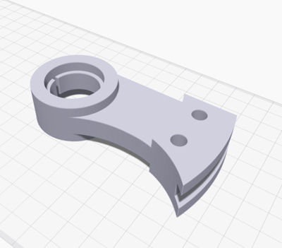
Let's take the part shown below, a holder for an optical breadboard.
The goal is to determine which pressure settings will produce a part that meets or exceeds the safety factor requirements while minimizing material costs, as 250 of these parts will be manufactured.
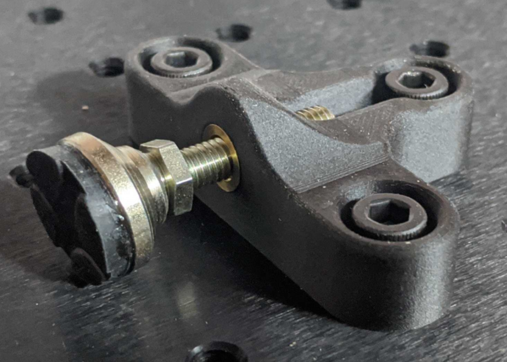
3D-printed holder for an optical breadboard
The part must be able to withstand a maximum load of 400 N without failure. A target safety factor of 1.5 takes into account uncertainties in the loading and helps ensure that the component does not fail during operation.
Initially, the user can validate the performance of the base part—which uses Onyx's default settings—with simulation. The minimum safety factor is 1.06, which falls short of the 1.5 requirement.
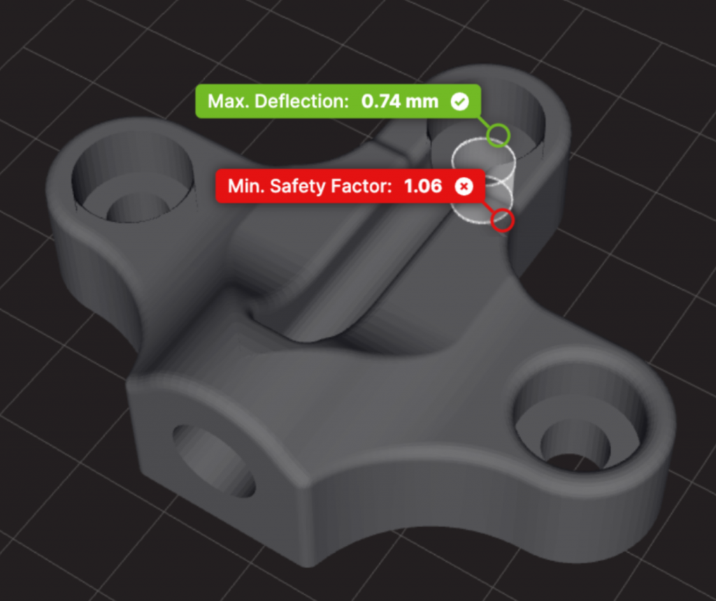
Simulation results for the base part using Onyx's default settings
To increase strength, the user can add continuous glass fibers to the part in all layers using isotropic routing. After this strength increase, the simulation predicts a safety factor of 2.74. While this part is now much stronger than the standard part, it comes at a price—material costs and print time have also increased significantly.
Since the safety factor is much higher than necessary, it's possible to reduce the amount of fiberglass and thus significantly lower material costs. This is where fiberglass sketching comes in.
When sketching the fiber overlay, fiberglass is added only in the area of the part that will benefit most—the load-bearing area (between the load and the primary fastener). After sketching the fiberglass, the simulation shows a predicted safety factor of 1.58: This means this part exceeds the strength requirements despite using far fewer fiberglass.
Compared to the same part with glass fibers in all layers, the cost of each simulation-optimized part is 37% lower and the print time is 44% shorter. These savings add up quickly with each print job. For example, a production run of 250 optimized parts results in savings of $1,197 in material costs and 34 days of print time.
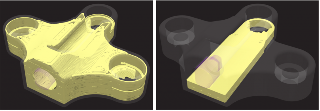
Continuous fiber placement (yellow areas) in the part with fibers in all layers (left) and in the part with fiber overlay sketch (right)
Simulation results for the 3 subconfigurations:

Summary
Eiger's new sketch feature for fiber overrides reduces material costs by providing more control over fiber placement. This new feature complements the benefits of simulation. Using both features together makes it quick and easy to obtain a performance-tested part without consuming excessive time and continuous fibers.
Fiber overlay sketching is now available to everyone in Eiger. Simulation is a feature available in the Advanced Digital Forge subscription tier. Contact us to learn more about Simulation.
For more information about continuous fibers, check out these resources:
Learn more about the applications with the MarkTwo!
Which continuous filament is suitable for which application? How do I design correctly for filament 3D printing? What do users say about it, and where can I find more information? – You've come to the right place! We've listed several information sources that will help you get the answers you need.




Leave A Comment