Efficient Fiber Routing Techniques Part 2: Advanced Routing Options
Advanced fiber routing techniques
Designing for 3D printing requires just as much work as designing for any other manufacturing process, and especially with our high-strength 3D printer, considering your manufacturing method is essential. There are some geometries and techniques that work very well for some processes and less so for others—we hope to encourage you to think about how you can efficiently and effectively use our unique fiber milling method to increase the strength of your 3D printed parts. Last week, we looked at some basic fiber milling techniques, including sandwich panels, perimeter reinforcement, and shells, and described what the different reinforcement options do and how to use them correctly. In this post, I'll expand on some of the concepts from last week's post and show how you can strengthen your parts using more advanced fiber milling techniques.
Optimize for a specific direction of strength
While concentric reinforcement reinforces the perimeter of the part with fibers, sometimes reinforcement is necessary for a specific direction or loading scenario. In many cases, the parts you print require reinforcement in specific areas based on a known loading condition. You can effectively improve the strength of your part by orienting the fibers in this direction using our "Fiber Angle" option.
Conventional composite materials consist of many layers of composite fibers, and within each layer, the fibers are arranged in a specific direction, the "fiber angle." To create a uniform composite fiber layer, each layer is rotated by a specific angle relative to the previous one until the entire composite fiber layer is quasi-isotropic.
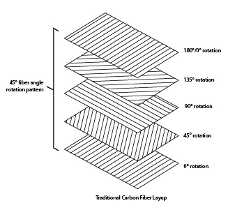
A traditional carbon fiber structure with different fiber angles per layer.
If you need strength in a specific direction, instead of constantly rotating the fiber sheets, you can orient them all in one or a few key directions. The fibers will align according to the part's loading condition, optimizing the part's strength in that direction. The part shown below is a drone arm, which primarily needs reinforcement along the length of the arm to prevent it from bending. By default, when reinforcing with isotropic infill, the fiber angles rotate to simulate a quasi-isotropic braid.
To efficiently reinforce this part, you can edit the settings of an isotropic fill part (either in the exterior or interior view) and set the fiber angles of each reinforced layer to 0. You can do this for a group of fibers or for a single layer. This will maximize the stiffness of the part along the length of the arm.
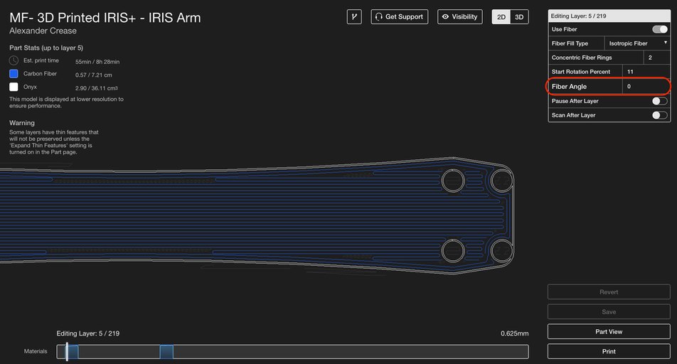
By adjusting the fiber angle of specific layers or groups, you can optimize the strength of your part in a specific direction.
This technique can also be extended to multiple directions – if there are two main directions that need to be reinforced, you can adjust the fiber angles to rotate between the two directions to make the part stable in both directions.
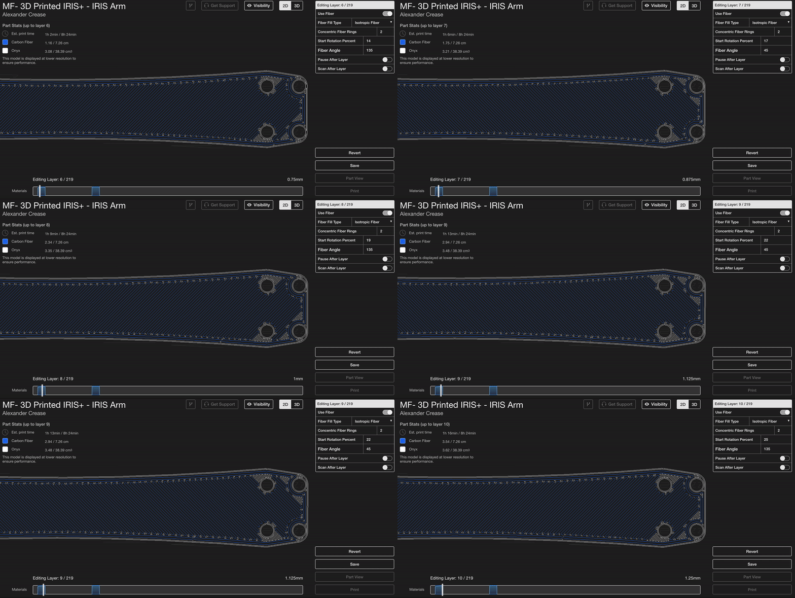
You can also set the fiber angles to rotate at specific angles.
Fiber striping
Fiber striping uses multiple sandwich panels stacked on top of each other to further stiffen the part during bending in the XY plane. If you have a thicker part with a fairly uniform cross-section, fiber striping allows you to further stiffen the part by stacking sandwich panels on top of each other to give it more uniform fiber reinforcement and much higher torsional strength.
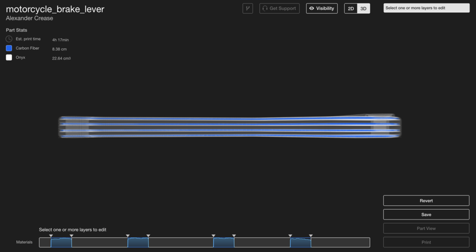
Fiber strips can achieve higher torsional strength in flat bending with sandwich panels placed on top of each other.
Selective reinforcement
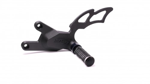
While fiber strips and shells are generally best suited for parts with a relatively uniform cross-section, sometimes it makes more sense to reinforce specific sections or features of the part rather than reinforcing them with evenly distributed fiber strips. In these cases, some considerations must be made to ensure your sandwich panels remain uniform. The part pictured below, a rear footpeg mount for a customer STS Turbo motorcycle, can be divided into two sections: the upper wing section, which prevents the rider's foot from getting too close to the rear tire's suspension, and the load-bearing bracket section, which contains bolt holes for attaching the footpeg and mounting it to the rest of the motorcycle.
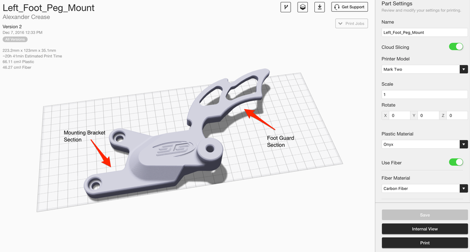
Each section of this part needs to be reinforced differently – a sandwich panel that extends the entire height of the part would be unbalanced.
The component needs to be stiff and resistant to bending, but a standard sandwich panel can't reinforce the component as much as we need—adding fibers to the top and bottom layers will result in an uneven sandwich panel and, ultimately, component failure. To overcome this problem, we can create two uniform sections of the sandwich panel—one enclosing the toe guard section of the part and one enclosing the part's support segment. This is called selective reinforcement—we define specific areas that need reinforcement and ensure the sandwich panels evenly confine each area.
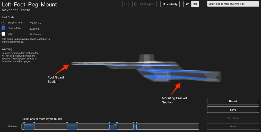
Each section is reinforced with a balanced sandwich panel for optimized reinforcement.
The part must then be further reinforced around the bolt holes to locally improve the strength of the part and to support the weight of the foot bolt, which is bolted to the foot bolt spacer at the top of the part.
Combinations
The granularity of layer-level control provided by Eiger allows you to efficiently strengthen in more than one way—all of these methods serve as guidelines for strengthening and can be used together in many different ways. In last week's post, I described how shelling with isotropic and concentric fill can ensure a stronger part, and similar procedures can be implemented using these techniques.
The footpeg mounting example I used above is an efficient fiber routing method to resist in-plane bending with selective reinforcement, but may require more strength for a reliable and robust solution. The wing portion of the part is non-structural but should resist in-plane bending, while the mounting pattern portion is subject to compressive loads from the bolts that hold it in place and torsional loads, as the footpeg supports the rider's weight. To reinforce the bolt holes, I insert a section of plies below the counterbore. This section of fiber is relatively central in its area, so another ply to balance the sandwich isn't necessary.
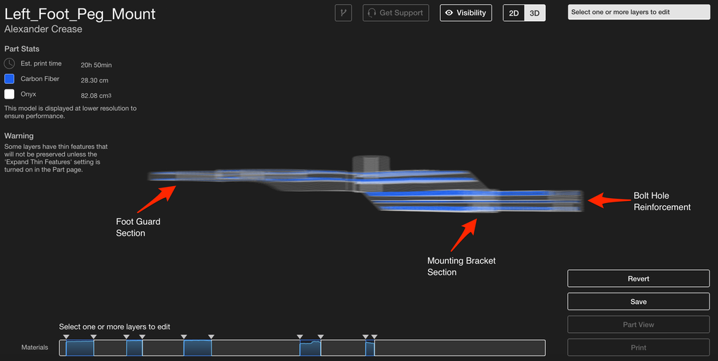
A carbon fiber center section reinforces the screw hole and provides additional flexural strength.
Next, I'll wrap the lower section of the part to improve its strength when flexing around the Z-axis, so it can withstand the rider's weight, as I described in our previous post. Finally, I'll add a concentric fiber reinforcement to the top of the part. This will increase the compressive strength of the part once the footpeg is bolted on and improve the torsional strength of the part, preventing the footpeg from twisting down and out of the hole.
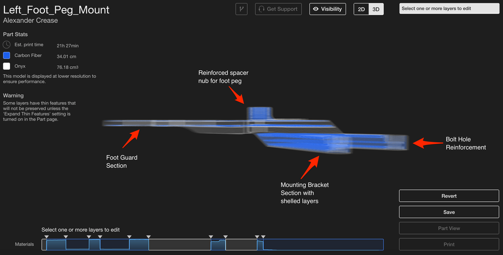
This part has now been reinforced using several techniques to improve the strength of the part in different areas.
The component is now selectively reinforced using various fiber placement techniques, which will be covered in this series of articles. If you have any questions, please let us know, and I hope we've helped you improve your fiber placement skills!

The printed footrest mount with optimized reinforcement.
If you don’t have a Markforged printer yet but would like to see one in action, you can request a demo here and check out our Try out Eiger software.
Learn more about the applications with the MarkTwo!
Which continuous filament is suitable for which application? How do I design correctly for filament 3D printing? What do users say about it, and where can I find more information? – You've come to the right place! We've listed several information sources that will help you get the answers you need.





Hinterlasse einen Kommentar