We tested new possibilities with Onyx, our new composite. One of our discoveries was that Onyx's surface texture and dimensional stability make it particularly well-suited for special bonding shapes.
In woodworking, joints are often created using specially coordinated geometries. Ideally, no additional fasteners such as nails or screws are required. This simplifies the assembly process, but the design is complex.
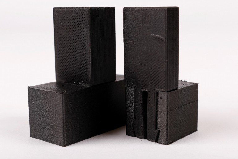
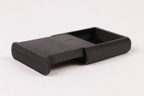
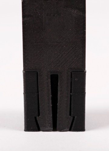
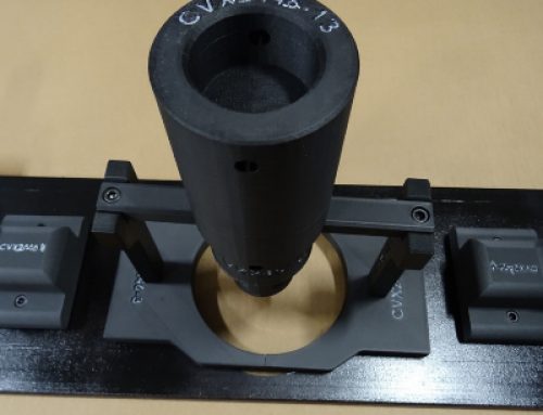
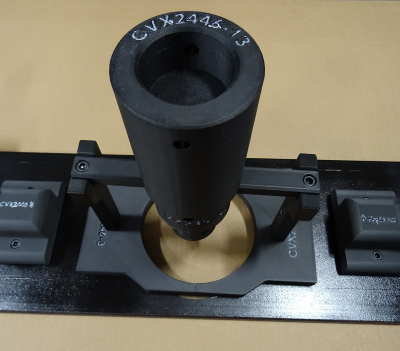
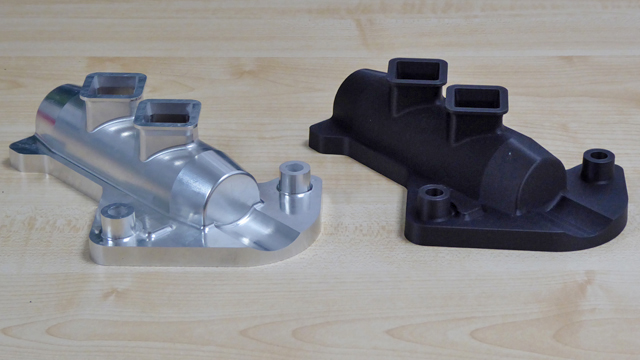
A classic T-rein joint, printed with onyx.
In 3D printing, printing complex geometries is often no more expensive than printing a block. Instead, FFF printing is limited by material properties and the layered structure of the part. By taking advantage of this geometric freedom, you can reduce the effort and cost of final assembly. The following section discusses what you need to consider during the design process to achieve exactly this.
dovetail
A classic dovetail joint.
When two parts need to be joined together, right angles seem like the obvious choice. These are usually efficient because they're generally much easier and faster to create than odd angles, require less setup, and don't require special bits or indexing tables. However, this isn't a problem with 3D printing. Dovetails are easy to produce. This is useful everywhere, whether you need a sliding mount or a lockless T-joint.
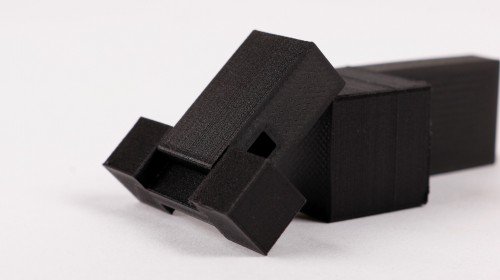
Box with sliding dovetail closure, disassembled.
The flared walls and tight tolerances allow this box to slide smoothly.
The established dovetail shape isn't the only option. The connection of the two-part sliding box above is equivalent, but looks more like a plate with angled sides. This allows for easy opening and closing. The lid even clicks into place at the end, keeping the box closed. Unlike most other machines and devices, the Mark Two can print this shape cleanly and accurately without any additional materials.
In other areas of 3D printing, too, the effort can be reduced through well-designed angular geometries. The V-profile, shown on the left in the image below, would be difficult to produce conventionally but easy to print. In contrast, the overhang on a classic tongue and groove joint (right) would lead to inaccuracies in the print due to the poorly supported underside.
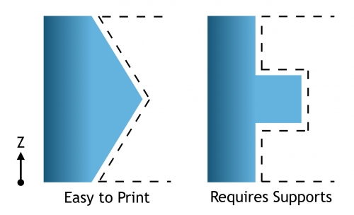
Profiles of a lateral V-wall (left) and a tongue-and-groove joint (right).
Request a sample component now!
See for yourself how strong the components are.

Snap fasteners
A frequently used method for cost-effectively joining injection-molded parts is the use of snap fasteners. Plastics are particularly well-suited for this because they can deform elastically and then snap back into shape. Snap fasteners are also excellent for printing, but the arrangement of the part on the layers must be strictly observed. Due to their layered structure, 3D-printed parts are more likely to break along the Z-axis (perpendicular to the floor of the printer). The snap fastener must therefore be printed horizontally to remain functional even after repeated use.
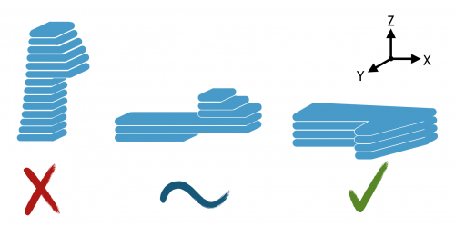
Schematic of the cantilever snap connection, printed in three possible orientations.
This diagram illustrates the layers of a printed snap fastener. When it's upright (shown on the left), bending forces create tension between the layers, increasing the risk of breakage. A snap fastener printed on its back (shown in the middle) is definitely stronger, but the best option is to print on its side (right). For even greater strength, composite fibers can now be routed all the way into the front tooth. The same applies to gear teeth, ratchet teeth, and other protrusions that must withstand significant loads.
Don't forget that snap fasteners can come in many shapes. You have complete freedom in terms of thickness and shape, allowing you to be creative. Prototypes are quick to produce, so you can test out a few geometries before settling on the final shape.
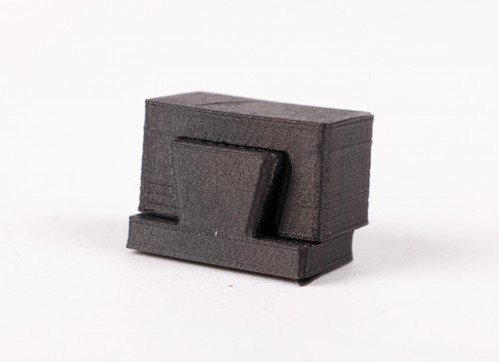
A flush snap fastener with a tenon joint.
Cross section of the flush snap fastener with tenon joint.
Assembled: Mobile phone holder
To demonstrate sliding connections and snap-on mechanisms, we designed this mount for the Mark Two. It holds any phone between 2.5 and 4 inches, allowing the operator to record a time-lapse video or monitor a sensitive print.
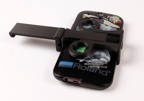
The cell phone holder holds a cell phone.
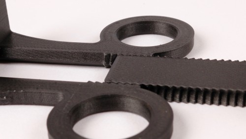
This phone mount has only three parts, two interfaces. One of these acts as a hinge. Although it doesn't look like a dovetail, it serves the same purpose: It allows for an easy-to-print, sliding fit thanks to complementary angles.
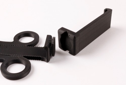
Disassembled phone holder (left) and hook (right).
Rotation joint clicks into place.
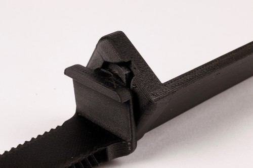
The other interface acts like a linear ratchet with angled walls and teeth. This adjusts the width of the holder. This would be very difficult to manufacture using most other means, but is quick and easy to print.
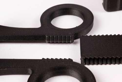
The teeth of the linear ratchet with the corresponding counterpart (right).
The ratchet is inserted.
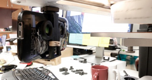
The mobile phone holder in use on the Mark Two.
A note on tolerances
As with everything, tolerances must be considered here. With the Mark Two, a gap of 0.08 mm between two walls is usually sufficient to achieve a sliding fit. When using supporting materials, the gap should be at least 0.15 mm. Perfect your results with unit tests and prototype analyses.
This is just one example of how well-planned connections can facilitate and improve printing and assembly.
Learn more about 3D printing with continuous fibers!
Which continuous filament is suitable for which application? How do I design correctly for filament 3D printing? What do users say about it, and where can I find more information? – You've come to the right place! We've listed several information sources that will help you get the answers you need.


Great post. Thanks for sharing! Can colored objects also be printed?
Hello Mr. Hermann,
Colored objects cannot be printed. However, the components can be colored later.
Best regards, Jonathan Schlawer
I also think the article is great – it helped me a lot
Super helpful. Are the 3D models also available for download or purchase?