Markforged Mechanical Features
Most 3D-printed plastics aren't strong enough for printing threads. Their yield strength is significantly lower than that of metals. Even fiber reinforcements don't protect against excessive wear. Precision and high connection strength can only be guaranteed with metal threads.
We've previously explained how to overcome this problem using heat and threaded inserts. The metal insert melts and bonds to the plastic. This can often be a good solution, but it also imposes design limitations. The insert must be applied to the front of a part, and its pull-out strength is limited by the material properties of the surrounding plastic.
A threaded insert is incorporated into a 3D printed part using heat.
You can work around the insert. You may know this technique as "overprinting," "co-processing," or "embedded printing." The process is similar to overmolding in injection molding, where parts are placed in the mold and the material is poured around them. This is how scooter wheels are manufactured, for example. The rubber tires are cast around the metal hubs.
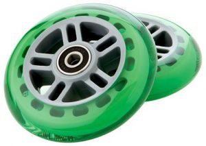
Wheels of a Razor scooter. The polyurethane tire is molded around the wheel's plastic hub. (Source: Razor)
overview
We can also use this technology in 3D printing. We pause the print and embed external components. This allows us to create assemblies that were previously considered impossible to manufacture. The insert is completely embedded in the print. When held in place by fiber-reinforced material layers, extremely durable screw connections are possible. All you have to do is design a recess of the appropriate size, pause the print just before adding the top layer, insert the component, and continue printing.

Design guidelines:
- Tolerances: When embedding components in 3D-printed parts, the printer's tolerance is the most important factor. On the Mark Two, a gap of 0.05 to 0.08 mm on each side ensures a good fit. To be on the safe side, be sure to check this on your printer. If the gap is too large, the print material won't bond sufficiently with the insert, and if there's too little space, the insert won't fit.
- The surface: The surface of the part you're embedding is also important. If it's smooth, you'll likely continue printing directly over it. You can apply some adhesive to the part when doing this. If the surface isn't flat, you shouldn't touch it during the rest of the print. In any case, the top of the embedded part must be below the print head, otherwise it will run into it. While designing, pay attention to the surface and when to pause the print and insert the part.
- Support material: Ideally, you don't need supports where you plan to embed parts, as they would otherwise collide. If unavoidable, you must remove them before inserting the part. You must also ensure that you are not printing in the air or on the insert.
- Selecting the Nut: Square nuts are actually the most suitable for this application, as they are difficult to deform even under severe twisting. However, since hex nuts are more common, I'll be using them in the following. If you plan to use this method frequently, square nuts would be a wise investment.
Summary of the procedure:
- Using your CAD program, you insert a hexagonal cavity into the component to be printed at the desired location.
- Load the component into Eiger and activate the pause function before the top layer of the cavity.
- Start printing and insert the nut during the pause.
- Then simply click on “Resume” and make sure that the nozzle does not hit the nut.
Embed nuts in the XY plane
1. Design the recess: Once you've designed the hole, measure the nut to be embedded and add a recess of the appropriate size. It's best to construct a guide plane for this purpose.
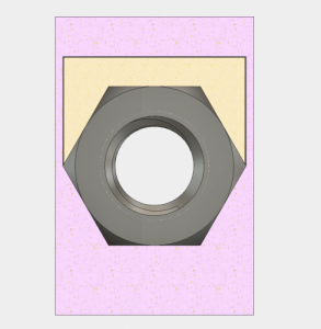
The plane on which I draw the sketch for the cutout.
I'm using an M5 hex nut (width 7.85 mm, height 3.85 mm). The specifications in the data sheet are inaccurate (8 x 4 mm), so I measured it manually. Now I have to add the tolerances (0.05 mm on each side). This gives me a width of 7.95 mm and a height of 3.95 mm. However, I want to make sure the nut fits, so I'm rounding up to 8 x 4 mm.
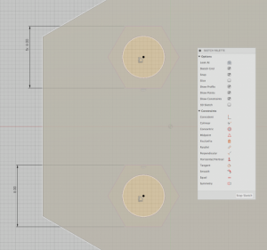
Sketch the nut profile including tolerances on the plane.
Draw the sketch as previously calculated. Do not fillet or chamfer the edges, otherwise you won't be able to insert the nut into the part later.
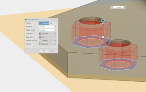
Extrude the sketch to create the cavity.
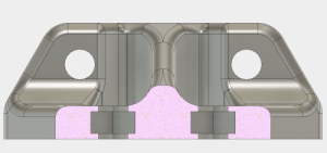
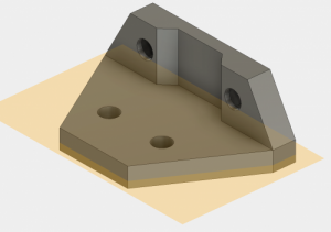
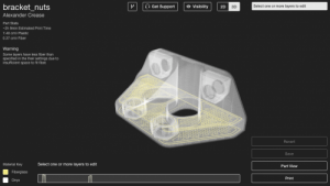
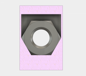
A cross-section of the nut holes for the bracket.
2. Add a break: In Eiger, you can add breaks at set levels. First, make sure you've turned off assist (unless absolutely necessary). This is done under "Advanced Settings."
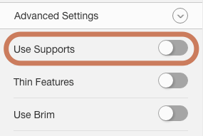
Support is turned off in the advanced settings.
Find the first ceiling layer of the cutout and scroll to the layer before it. Click "Pause after layer" to insert the break.
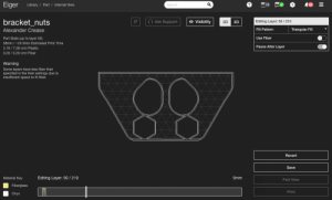
Insert a break using the “Break after level” function.
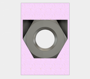
3. Add fibers: To increase the holding power of the nut, you can add fibers above or below your part. In the image below, I've added fibers on both sides of the nut for better grip. They can also be placed on the six side walls, which prevents the nut from twisting.
Fibers above and below the nut prevent it from being pulled out.
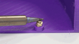
4. Printing the part: Now it's time to print. In the layer details in Eiger, you can see when the print is paused, so you don't have to wait. During the pause, slide the component into the recess and resume printing. To ensure the nylon or onyx adheres securely to the part, you can apply a little of our glue before resuming (Caution! The glue can cause layer delamination on the printed material itself!). To embed nuts in hard-to-reach places, you can safely remove the base plate from the printer and reinsert it later. The kinematic couplings on the underside snap back into their starting position with 10 micron accuracy.
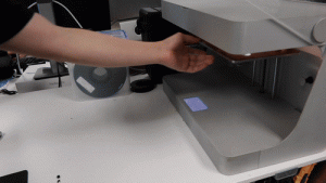
Simply remove the base plate, insert the nuts and continue printing.

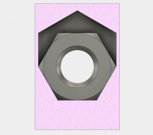
The embedded nuts of the 3D printed part.
5. Handling support material and more complex geometries (if necessary): If you need to use support material, you can remove it with flat-nose pliers during the pause. However, this only works if your cavity has a flat ceiling. If you're embedding parts with more complex surfaces, you won't be able to use support material. You'll either need to use curved or angled overhangs to keep the interior clean, or print a secondary part with a flat surface to remove the material. This process is described below.
Printing secondary parts to embed nuts on other planes
Adding embedded nuts on other levels requires design effort. A secondary part is required. As an example, I want to embed a hex nut into my part, as shown in the cross-section below, with its axis parallel to the build plate. (A square nut would be the simplest solution here, as it would provide a flat surface for printing.) Leaving the cavity as shown requires support material to be removed.
With a flat overhang, the sides of the ceiling are not supported.
I could install an angled overhang into the cavity. However, I still can't use support material, and on top of that, the nut wouldn't fit tightly and would twist in the recess when tightening a bolt.
With an angled overhang, the nut rotates in the cavity.
Instead, I can add a secondary part to the print that secures the nut and gives the printer a flat top to print on. To do this, I create a recess with a flat top for the nut:
With a little more space in the recess we can integrate a secondary part to secure the nut.
Design a small part that fills the remaining space in the cavity. Again, consider tolerances.
The nut can now be secured inside the cavity using a secondary part.
This can be printed next to the main component, so I can insert it during the break with the nut, and continue printing on the flat top of the secondary print part, like the angled square nut below.
Using the same method, you can also embed nuts at other angles; you just need enough space to place them. The small, rectangular piece in the cross-section view below secures a square nut crosswise in the printed part:
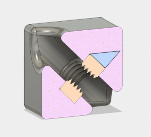
This cross section shows an obliquely embedded square nut secured with a triangular gap filler.
Secondary inserts allow screws to be driven at all angles.
This technique allows nuts to be installed at any angle and on any plane in 3D-printed parts. But you don't have to limit yourself to nuts. Experiment with how you can best use nuts or other components and share your results with us.

I think the suggestion with the additional part is excellent. The example with the nut is also very suitable.
However, embedding the nut shown can be simplified by rotating it by 30°. This creates vertical side walls (instead of a flat bottom). The top then has a slope, which some printers can even print as an overhang without an additional part.