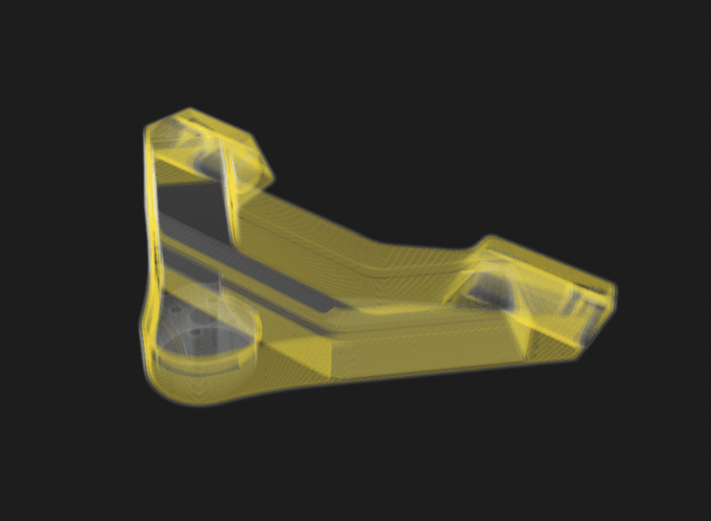
Reinforcing 3D-printed parts with efficient fiber placement: Part 1
Types of fiber fillings
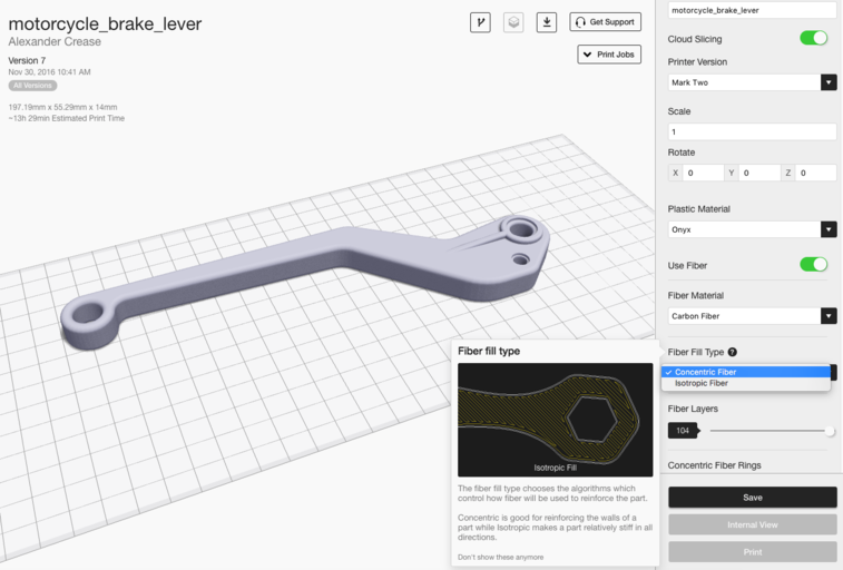
By choosing the right fiber installation option, you can save time and material while maintaining strength.
Our high-strength 3D printers offer two different fiber filling strategies for reinforcing 3D-printed parts: Isotropic Fiber or Concentric Fiber. You can apply these two options globally on the Part View page or layer by layer on the Internal View page. The unique reinforced 3D printing process offers users a variety of reinforcement tactics to choose from. Each fill type has its own strengths and weaknesses, which we describe below. If you don't have a Markforged printer and would like to experiment with some of the tips listed below, you can request an Eiger trial to try these tactics for yourself.
First, some standard naming conventions to keep everyone on the same page. I'll be referring frequently to strength in different axes and planes, so use this key as a guide:
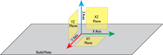
How we define the axes of our printer, a convention I will use in this post.
Concentric filling reinforcement
Concentric filling simply traces a specific number of shells within the outer contours of your part, helping to prevent the part from bending around the Z axis. This essentially reinforces the part's walls, preventing wall deformation.
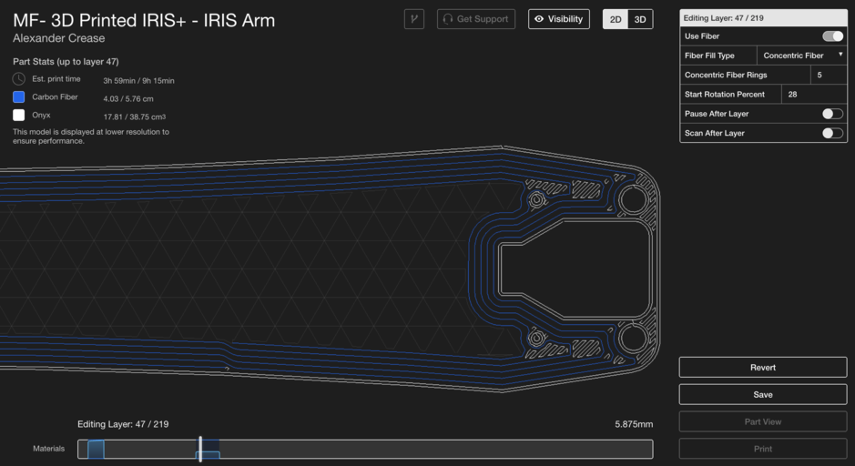
A drone arm with concentric fill reinforcement to increase flexural strength and save weight.
Concentric filling typically takes longer because the print head movements are no longer linear, so the print head must slow down to ensure accurate toolpath tracking around curves. With this type of filling, the print head follows the outer curve of the part while spiraling inward; the more complex the curve, the longer it takes. With concentric filling, you can specify how many fiber rings should trace the contour of your part, giving you good control over how much fiber you use per layer.
Isotropic filling reinforcement
Our continuous fiber 3D printers can also print with an isotropic fiber fill pattern—this simulates the individual unidirectional layers of a conventional laminated composite. The pattern effectively creates a unidirectional "sheet" of fibers on each layer you apply it to, laying all the fibers parallel to each other in a single angular orientation, with 180-degree rotations as the path reaches the edge of the part. Subsequent Isotropic Fiber layers in a fiber group are automatically rotated by Eiger at a 45-degree angle to the orientation of the fibers in the previous layer, although custom orientation patterns are also possible, which we'll cover in the second part of this post. The Isotropic Fiber fill pattern helps resist bending in the XY plane because any bending forces acting in this plane create a tensile load on at least some of the fibers, which are strongest in tension. Isotropic fibers can also be used to construct sandwich panels to increase torsional strength in this plane, which I will describe later.
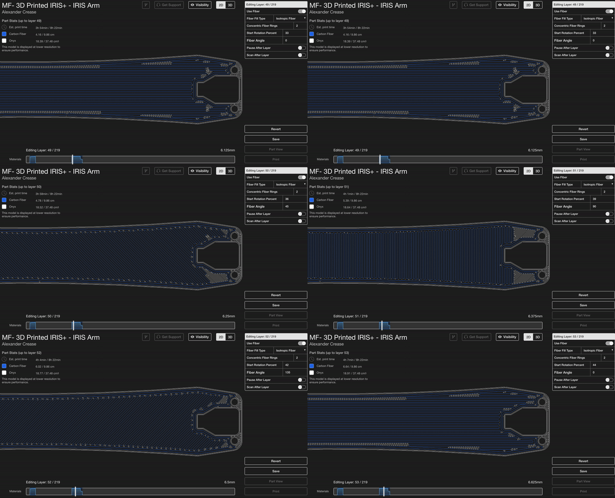
Several layers of isotropic fiber filling. The fiber direction rotates by default.
You'll notice that isotropic fibers, by default, create two concentric fiber rings around the outside of the part. This ensures a uniformly reinforced outer surface, as the outermost fibers are always continuous and parallel to the edge of the part. While isotropic fibers are excellent for reinforcing the entire plane of a part, they are fiber- and time-consuming and not always necessary for producing strong parts.
Basic techniques of fiber laying
With these two fiber placement options in your toolbox, there are now many different reinforcement options that utilize and combine both. These techniques can help you save money, material, and printing time by reinforcing only where needed.
Single sandwich panel
A sandwich panel is a common composite layup technique for torsionally strengthening the surface that forms the composite panel. As described in this blog post, a sandwich panel is the composite equivalent of an I-beam, where a stiff, strong material forms the top and bottom of a part—the top and bottom are subjected to the greatest bending stress and are therefore often the most reinforced. If you know your part will be subjected to torsion in the XY plane, a sandwich panel improves the part's torsional strength.
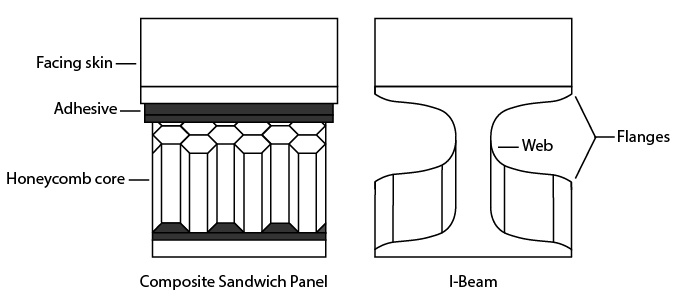
Like an I-beam, a sandwich panel is reinforced primarily at the top and bottom to maximize strength and minimize weight.
Our software automatically creates a sandwich panel when "Use Fiber" is selected. However, this should only be done if your part is symmetrical, as the fiber will be routed in the top and bottom layers of your part. In the image below, you can see that the top of the brake lever is actually a small extrusion, so the fibers must be added manually—it makes more sense to place the fibers under the largest surface near the top of the part. In general, it's best to have a sandwich panel composed of layers with very similar cross-sectional areas.
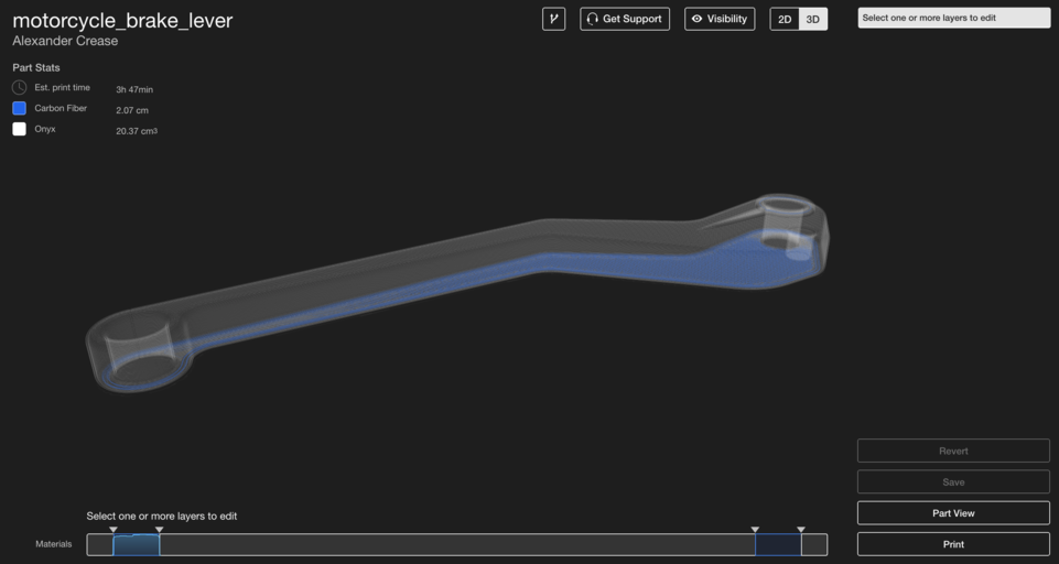
This brake lever with the standard settings of the sandwich plate. Because the part is asymmetrical, its fiber settings must be adjusted.
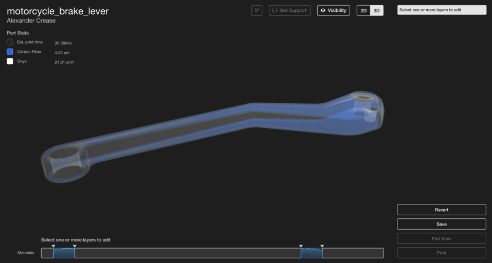
By changing the placement of the top layer, I can make the sandwich panel flat.
To ensure the sandwich is uniform, it is important to ensure that the number of isotropic layers on the top and bottom sides to be reinforced is equal. Sandwich panels must be uniform; otherwise, the part will bend more in one direction than the other and may break or warp more easily in one direction. The more fiber layers there are on either side and the greater the spacing between each layer, the stronger the part will be. Isotropic fiber layers in the center of the part have less effect on the part's flexural strength, so it is not necessary to completely fill a part with fiber to increase flexural strength.

The distribution of bending stress on the profile of a beam.
Fiber Perimeter
While sandwich cladding increases strength around the XY plane, creating a fiber perimeter around the Z axis makes your part stronger. By using the Concentric Infill option on each layer of your part, you can increase strength when bending around the Z axis. As mentioned earlier, concentric infill reinforces the walls of your part, so creating a fiber perimeter in your part makes those walls much more difficult to bend. This is why many engineering materials are shaped like C-channels or tubes instead of blocks: to reduce weight but maintain strength.
To create a fiber girth in your part, use concentric fillers in the layers you want to reinforce. By increasing the number of concentric rings or the number of plies where concentric rings are used, you can increase the strength of the part around the Z-axis. The brake lever shown below will experience bending stress around the Z-axis, so I reinforced each ply with 3 rings of concentric fibers to maximize stiffness. As with sandwich panels, the bending stress is lowest in the center of the part, so the part doesn't need to be reinforced with rings all the way to the center.
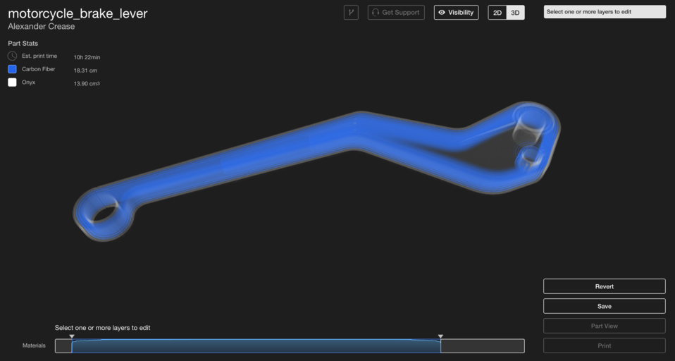
The brake lever only needs to resist bending around the Z-axis, so only concentric filling is required.
Peel
What if your parts need increased bending stiffness in every axis, or you're unsure how they'll be loaded? Combining these two techniques allows you to strengthen parts against bending around any axis. Using a sandwich plate on the top and bottom, with fiber shells in between, will improve your part's bending stiffness in every axis. This motor mount for a high-performance robot application needs to be strong, but can be subjected to loads from all directions, so it needs to be heavily reinforced on all sides.
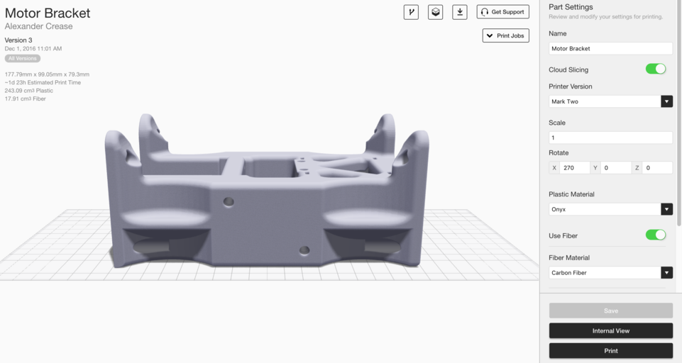
A large motor mount for a high-strength application.
I want this part to be very robust, so I chose 20 layers of isotropic fiber sandwich panels (10 per side). However, because of the bolt hole extrusions on the top of the part, I need to adjust the top fiber "panel" and place it under the top of the part.
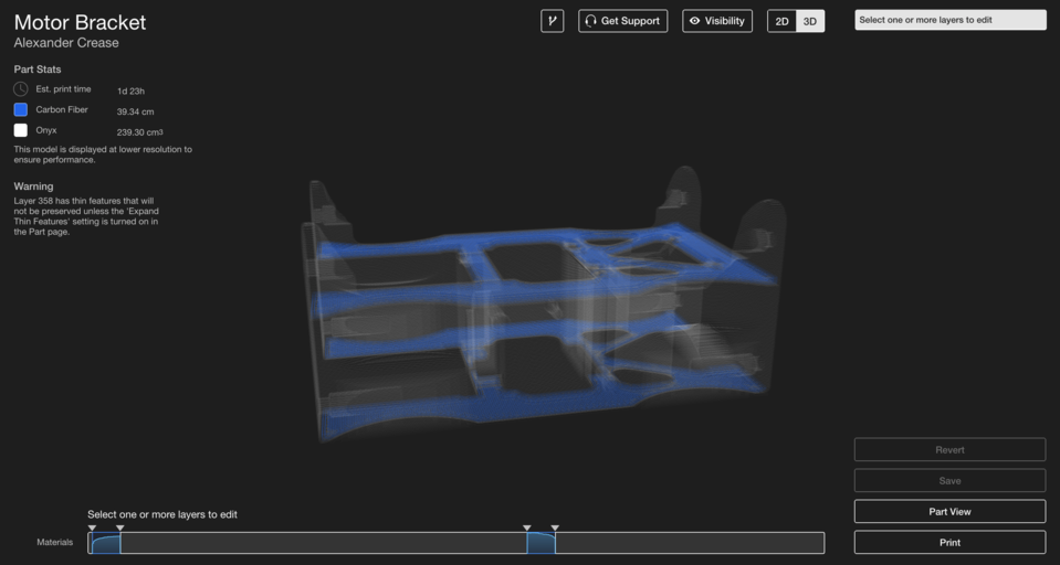
The engine mount with simple sandwich plate reinforcement.
The bar at the bottom allows you to control different fiber sections and shows how much fiber each layer has, normalized to the largest fiber amount. In the image above, you can see two sections of fiber reinforcement for a simple isotropic sandwich panel. Now I can select the middle area between the two "panels," create a group, and set the fiber routing to Concentric Fiber Fill with 2 concentric fiber rings.
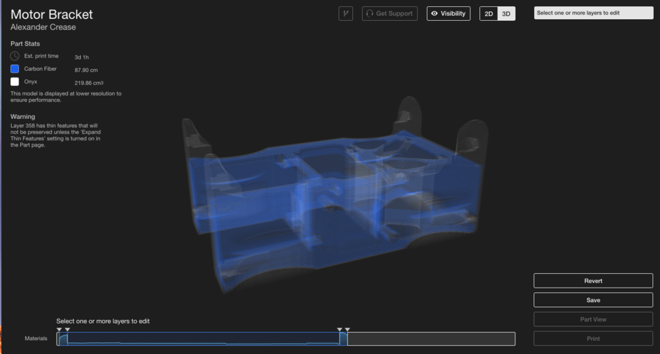
Concentric fibers between the sandwich panels form a fiber shell inside the part, ensuring optimal strength.
This part is now efficiently reinforced during bending through the use of isotropic and concentric fiber fills. By understanding how each type of fiber fill configuration strengthens a part, you can develop simple tricks like this to improve part performance and print time without wasting unnecessary fiber. Stay tuned for the second part of this post, where we'll cover more advanced techniques for optimizing part strength using fiber alignment!
Want to learn more? Request an Eiger trial to experiment with our software and fiber reinforcement options. Check out the second part of this post, which covers advanced fiber placement techniques!
Learn more about the applications with the MarkTwo!
Which continuous filament is suitable for which application? How do I design correctly for filament 3D printing? What do users say about it, and where can I find more information? – You've come to the right place! We've listed several information sources that will help you get the answers you need.





Hinterlasse einen Kommentar