
Reinforcement of 3D-printed parts with efficient fiber placement
The different types of fiberfill

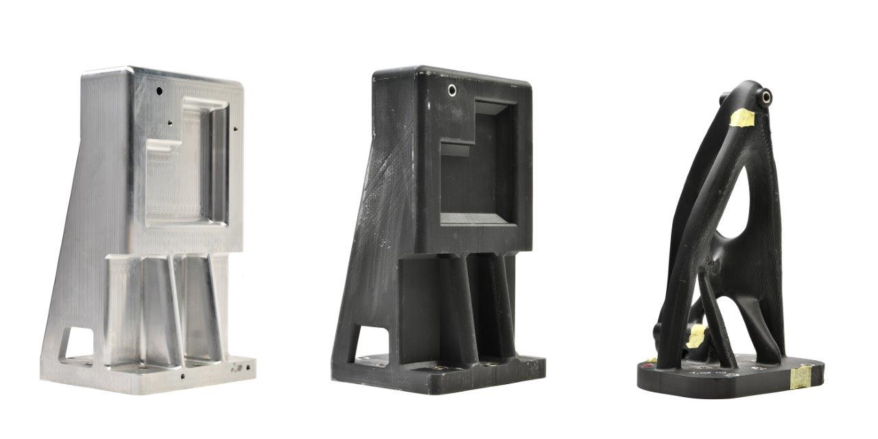
By choosing the right fiber installation option, you can save time and material while maintaining strength.
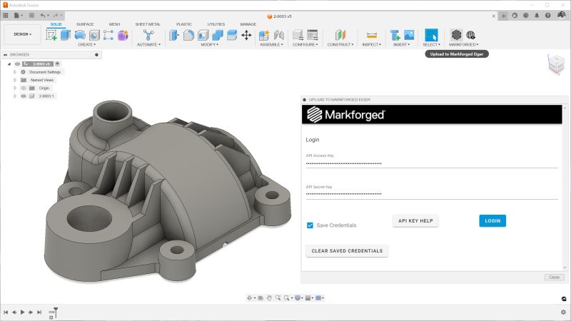
Our high-performance 3D printers offer you two different fiber filling strategies for reinforcing 3D-printed parts: Isotropic Fiber Placement or Concentric Fiber Placement. You can apply these two options globally in the "Part View" selection or layer by layer in the "Interior View" selection. The unique reinforced 3D printing process offers the user a range of reinforcement alternatives to choose from: Each fill type has its own strengths and weaknesses, which we describe below. If you don't have a Markforged printer and would like to experiment with some of the tips below, feel free to try out the different options in the Eiger test version from.
First, some standard name definitions to get everyone on the same page. We will often refer to strength in different axes and levels, so use this key as a guide:

This is how we define the axes of our printer
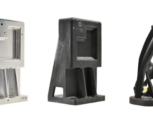
Concentric fiber reinforcement

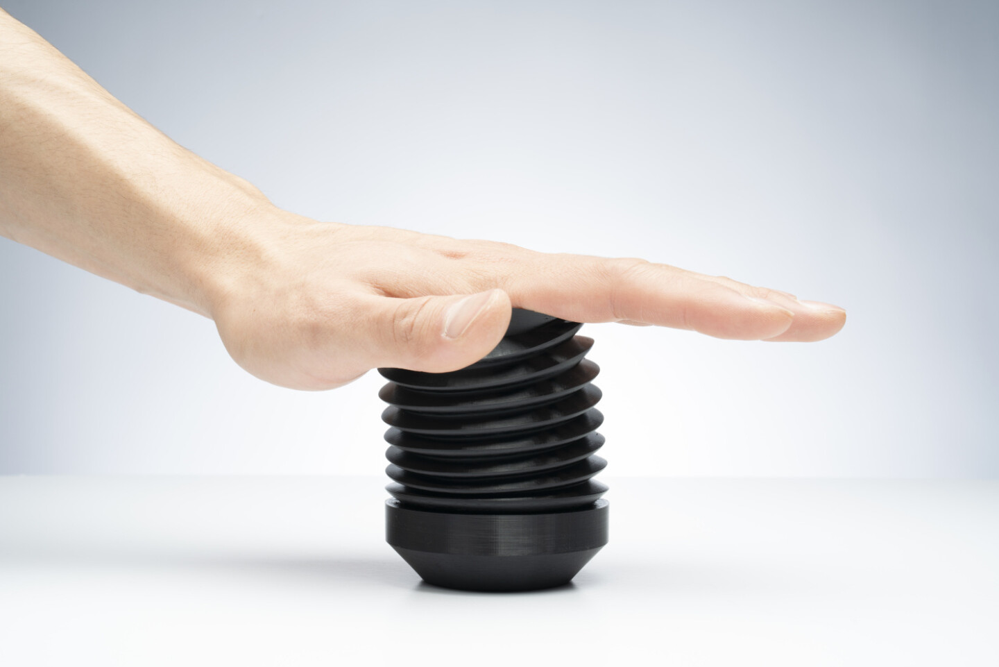
A drone arm with concentric filler reinforcement to increase flexural strength and reduce weight.
Concentric filling tends to take longer as the movements of the print head are no longer linear and the print head must therefore reduce speed to maintain accurate tool path tracking in curves. With this type of filling, the print head follows the outer curvature of the part as it spirals inwards; the more complex this curvature is, the longer it takes. When using concentric filling, you can specify how many fiber rings you want to trace the contour of your part, giving you good control over how much fiber you use per layer.
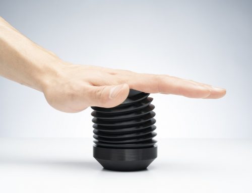
Isotropic fiber reinforcement
Our continuous fiber 3D printers can also print in an isotropic fiber fill pattern - this simulates the individual unidirectional layers of a traditional laminated composite. The pattern effectively creates a unidirectional "weave" of fibers on any layer you want to apply it to. To do this, all fibers are laid parallel to each other in a single angular orientation. When the path reaches the edge of the part, it makes a 180-degree turn. Subsequent isotropic fiber layers in a fiber group are automatically rotated by Eiger at a 45-degree angle to the orientation of the fiber in the previous layer. However, user-defined alignment patterns are also possible. The "Isotropic Fiber" filling pattern helps to resist bending in the XY plane. Any bending forces acting in this plane will create a tensile load on at least some of the fibers that are strongest in tension.

Several layers of isotropic fiber filling. The fiber direction rotates by default.
One thing you may notice is that, by default, isotropic fibers place two concentric rings of fibers around the outside of the part. This ensures a uniformly reinforced outer surface, as the outermost fibers are always continuous and parallel to the edge of the part. While isotropic fibers are great for reinforcing the entire plane of a part, they are fiber- and time-intensive and not always necessary to create stable parts.
Request a DEMO component now!
See for yourself how strong the components are.

Learn more about 3D printing with continuous fibers!
Which continuous filament is suitable for which application? How do I design correctly for filament 3D printing? What do users say about it, and where can I find more information? – You've come to the right place! We've listed several information sources that will help you get the answers you need.
Hinterlasse einen Kommentar