Markforged's composite fibers have incredible properties and can make many 3D-printed parts stronger and more stable. However, as with all manufacturing processes, composite-reinforced 3D printing can be used to particular advantage for certain applications. In CNC machining operations, for example, an end mill can only produce slots up to a minimum width, limited by the diameter of the selected tool.
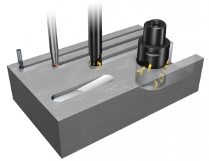
Cutting tools with different diameters each cut minimally wide slots (source: Sandvik Coromant)
Likewise, Markforged composite fibers have a fixed width and can only reinforce structures with a minimum width. It's not uncommon for a designed part to have a cross-sectional geometry that's too narrow for our composite filaments in a certain area. It's beneficial to consider the possibilities in the production process from the very beginning. To this end, we've created a practical guide to effectively designing parts for composite-reinforced 3D printing.
Reinforcement of narrow parts
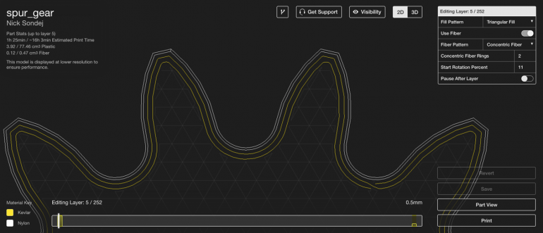
Markforged composite filaments are sandwiched between the outer nylon shells of a part. When reinforcing a thin section, you must use a concentric fiber ring in Eiger to ensure that only a single path is laid down. This is done with the "Concentric Fiber" or "Isotropic Fiber" fiber patterns. In the image below, I simply used the concentric fiber pattern to add a single Kevlar path. Specifying a number of concentric fiber rings allows Eiger to automatically reinforce the part with up to that number of rings, given sufficient space.
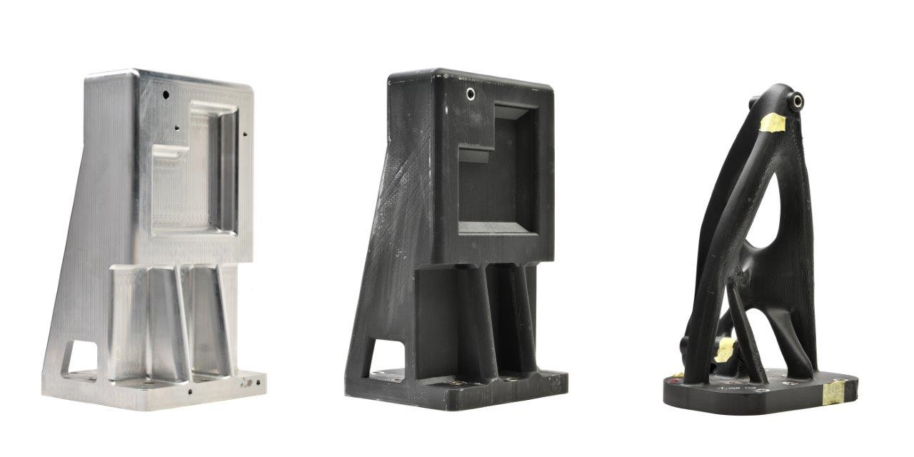
A single path of concentric Kevlar (yellow) runs through the narrow areas of the part shown here in cross-section.
If the cross-section of the part to be reinforced allows for a continuous loop (as in the image above), a single fiber path can be created to reinforce the part. The width of a fiber path is approximately 1 mm. With the two nylon shells on either side, the part to be reinforced must be at least 2.9 mm thick. This must be taken into account during the design phase.
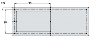
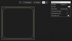
The minimum width of a part that can be reinforced with a continuous loop of Markforged composite fibers is 2.9 mm.
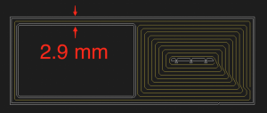
The thinnest section of this part is 2.9 mm wide, allowing the fiber path to be laid.
Turn back at the end
But what about thin sections that protrude from the main body of a part and are connected to it at only one end? This occurs, for example, in turbine blades or propellers. In this case, the fiber must enter the section, pass through it, and exit it again to form a concentric ring.

Note the carbon fiber paths (blue). The path leaves the turbine's rotor hub, travels around the tips of the blades, and returns to the hub.
In this case, two fiber paths must fit into the part to be reinforced. As we already mentioned, each fiber path is approximately 1 mm wide, resulting in a minimum width of 3.8 mm.
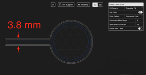
The minimum width of a fiber-reinforced secondary section is 3.8 mm.
Further applications
The rule of thumb described above is important for projections that require fibers at critical locations. These are primarily sprockets and gears. For a gear tooth to be fully reinforced from root to tip, the tip must be over 3.8 mm wide.
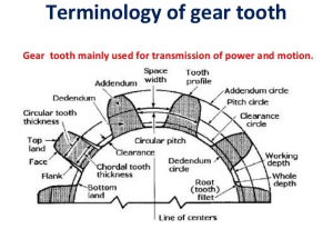
A detailed diagram of the various components of an involute spur gear (source: Slideshare)

The teeth on this gear are fully reinforced with Kevlar from the root to the tip.
Smaller gears and sprockets can be reinforced, even if the fiber can't extend all the way to the tip. The gear will still be stronger than a pure plastic one, but may be weaker locally at the tooth than desired.

In this smaller spur gear, the fiber reinforcement extends only slightly beyond the pitch circle of the gear.
- The minimum part width for a thin section connected to a larger section at both ends is 2.9 mm
- The minimum section width for a protruding area is 3.8 mm


Leave A Comment