3D Printing Software
[7 minutes reading time]
There are many and very different 3D printing software programs, but basically they all have the same core elements and analyze a common file type. There are four main steps to get from a part model to a 3D printed part: Import the part file from CAD into the software, turn the imported part file into a printable file, send one or more of these files to the printer, and manage your printers to maximize uptime and throughput.
From CAD to STL
The first step in 3D printing is to create a file that can be analyzed by the 3D printing software. While traditional subtractive machining is based on a combination of part drawings and computer-aided machining (CAM) files, 3D printers accept STL files. These files store 3D data by decomposing the surfaces of your part into a triangle mesh. They can be exported from almost any CAD program. There are a few important factors to consider when exporting these files:
Mesh – quality vs file size: When exporting STL from CAD software, you can determine the density of a triangle mesh. Large meshes produce smaller file sizes that are processed faster, but produce parts that can be multi-faceted and inaccurate. Small meshes produce realistic, accurate parts, but produce huge files that may be difficult for your 3D printing software to handle. When you know how your part is used, you know what priorities to set.
STL resolution is an important factor when exporting a part for use in 3D printing software.
A line drawing of two halves of a sphere saved at different STL resolutions. The left side of the sphere is saved at a low resolution, while the right side is saved at a high resolution.
Multi-body parts and assemblies: When working with a multi-body part or assembly, be sure to export each part separately. If you export the entire file at once, the resulting STL often fixes both parts relative to each other so they cannot be printed.
If you don’t use CAD but still want to print a part in 3D, several large online libraries with printable STL files are available for free download.
Cut: From the solid to the printable part
3D printers rely on toolpaths to perform their tasks. These paths are automatically generated by a slicer in all 3D printing software. A slicer picks up a part, divides it into “planes” parallel to a reference plane specified by the user, and generates toolpaths that the print head can follow on each plane as it extrudes material. These toolpaths include “carrier material”: automatically generated sacrificial sections that ensure that hanging or cantilevered overhang sections of your part are supported during printing. While the whole process is automatic, there are some important parameters that you can control:
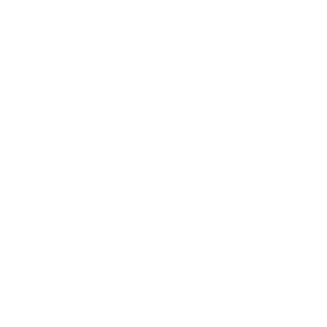
Part Alignment: The most important parameter to consider when setting up a part for printing is the orientation within the printer. Part alignment can have a massive impact on the success of printing and the strength of the parts, and is often a balance between strength requirements, critical dimensions and bed contact. 3D printed parts are stronger and more accurate, with their critical elements parallel to the printing bed. By aligning the part so that the largest face is on the print bed, print runs are minimized and printing success is improved.
The build orientation selection in your 3D printing software affects the way the 3D Slicer generates toolpaths.
In your 3D printing software, you can control how your part is aligned on the print bed.
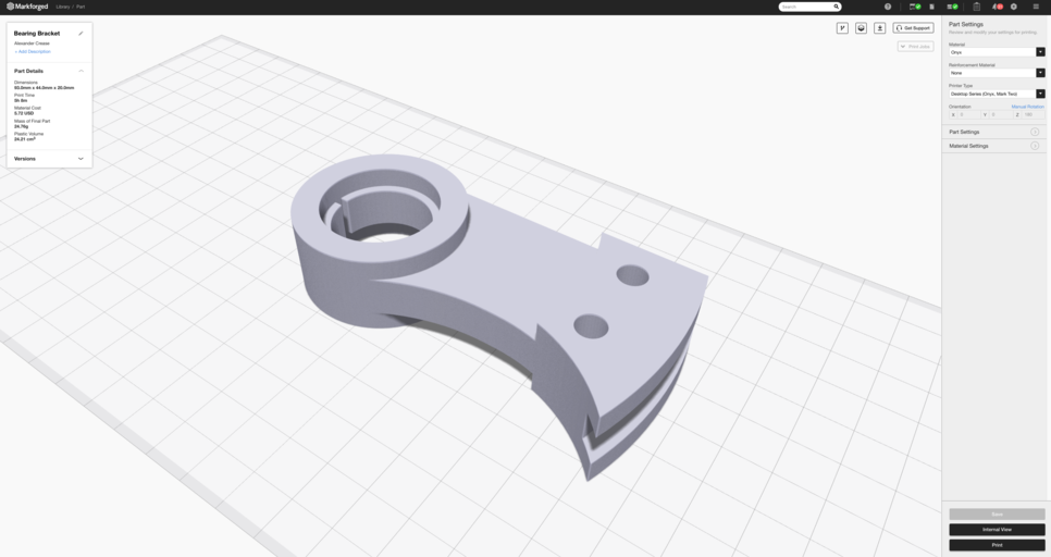
Layer height: In addition to the orientation of your part, the most important factor you can control is the layer height-the thickness of the layers that intersect your part. Larger layers produce a less accurate, lower resolution part that prints faster, while shorter layers produce a more accurate and detailed part that takes longer to print.
The layer height selection in the 3D printing software affects the print resolution and time.
A lower layer height takes longer to print, but provides a more detailed print.
Part Filling and Shell: FFF 3D printed parts are very rarely solid – mostly they are shells with a cell filling. Printing with this geometry reduces both printing time and material costs without compromising part strength. Markforged’s Eiger software uses a triangular fill by default, but you can change both the shape and size of the fill. You can also vary the number of layers at the top (roof), bottom (base) and sides (walls) of a part.

The 3D printing software generates shells, fillings and toolpaths for continuous fibers.
A representation of the cross-section of a continuous fiber reinforced 3D printed part.
Continuous fiber reinforcement: Markforged composite printers use a second nozzle to fix continuous, long strand of fibers into parts. You can control whether to use continuous fiber, how much to use, and how to lay it in your part. To learn more, click here to try our software for free.
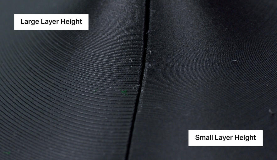
Send your part to your 3D printer
After your part is cut, it can be printed. If you print multiple parts with the same material and layer height, you can lay them out together in one build. A build can contain as many parts as will fit into the printer’s build volume, and is a great tool for organizing projects or parallelizing your 3D printing workflow.
You can send one or more parts to a 3D printer when it is sliced.
After you have created your build, it is time to send the build file to the printer. Some machines require you to use an SD card or USB drive to physically transport the file. Markforged printers are connected to the Internet, so you can digitally transfer your part over the Internet. After you send your part to your printer, you can monitor the progress from your computer.
Manage your 3D printer fleet
By effectively managing prints, you can double or even triple the throughput of your 3D printer. By scheduling your jobs during work hours, you can ensure that your printer is running almost all the time. Try some simple things to maximize your bandwidth:
Align your print jobs strategically: The only practical part of the 3D printing process is to remove your parts from the print bed and reset the printer. Maximize your print bandwidth by finishing printing while you are near the printer so you can quickly and easily reprint. Print longer jobs overnight and shorter jobs during the day to make the most of your working hours.
If your printing time is 0-8 hours (+ X days), start it at the beginning of the working day
If your printing time is between 8 and 16 hours (+ X days), start it at the end of the working day
If your printing time is between 16 and 24 hours (+ X days), put it down in the middle of the working day
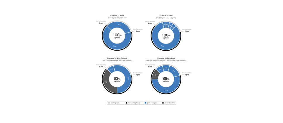
Some examples of how you can design 3D prints to maximize computer bandwidth.
Use the weekend for the largest parts: There are approximately 64 hours between the end of one working week and the beginning of the next. If you have a multi-day print, start it on a Friday to use as much of this bandwidth as possible.
Use builds, to take a strategic approach to printing times: Builds are suitable not only for organizing projects, but also for controlling printing times. If your individual parts do not fall into one of the optimized print times, combine them with other parts in the queue to make the print time work.
Learn more about 3D printing continuous fibres!
Which continuous fibre is suitable for which applications? How do I design correctly for filament 3D printing? What do users say and where can I find more information? – This is the right place for you! We listed some information leading you directly to the matching answers.

Composite Design Guide
DfAM – How do you design your part best for 3D printing with composites? In this guide you will get valuable tips for design and material selection.
3D printing in production
This free guide serves as a source of information for engineers and contractors who want to integrate a 3D printer into their manufacturing process.
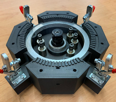
Primetall Case Study
In this practical case study from Primetall, 3D printing was used to print custom fixtures. It was practically “drilled around the corner”.

3D Printing vs. CNC Machining
The two production technologies each have various benefits and drawbacks, and this article identifys the applications which best benefit from one or the other.