Markforged Mechanical Features (MMF) is a blog post series about designing technical components for fiber-reinforced 3D printing with our Markforged 3D printers.
This is the start of the MMF blog post series. Our customers often ask us how their usual technical functional elements can be 3D printed. They want to take advantage of the properties of Markforged materials. In this and the following articles, we address such topics. Learn how to use your Markforged 3D printer most effectively!
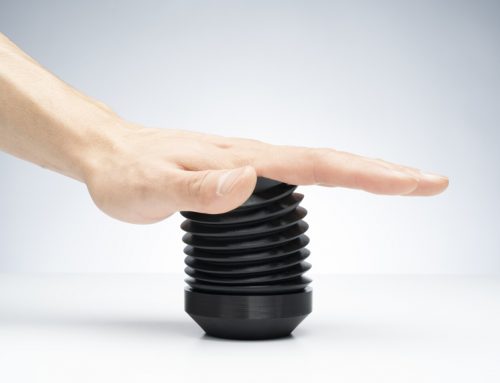
This post is about film hinges. Film hinges consist of a thin-walled element integrated between two components. This element is elastically deformable, allowing the part to be bent into a hinge. Because such connections are both robust and easy to manufacture, they are often found on plastic containers for consumer goods, such as shampoo bottles. You can produce your own film hinges with your Markforged 3D printer.
Technical terms
In the graphic below you can see a labeled representation of our example hinge.
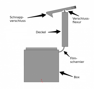
Note the film hinge and the locking flexure. Both elements are flexible and can only be bent around a single axis. Both elements are film hinges, but they serve different purposes. This is already indicated by their different geometries.
Bennett's film hinges
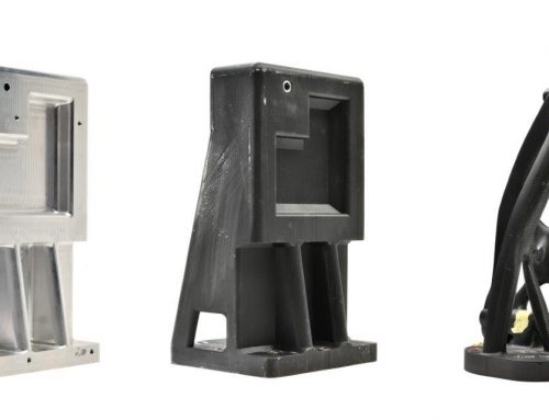
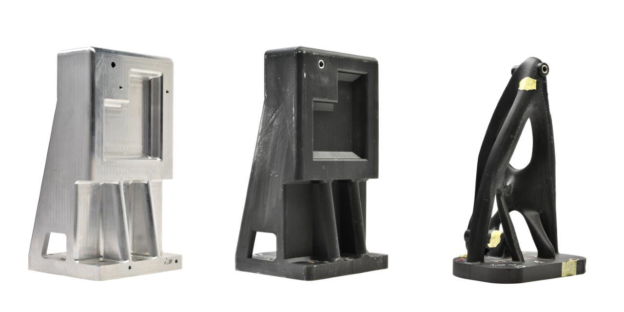
Bennett is a mechanical engineer at Markforged. He works with 3D models and enjoys improving components using 3D printing. His first 3D-printed hinges were sample parts designed by his brother. His brother works in consumer electronics, where snaps and hinges are an essential part of hardware design. Prototypes of this type are typically produced using a stereolithography (SLA)-based 3D printing process. This involves visualizing external shapes in multiple configurations. The materials used are brittle, and a hinge breaks after the first test run. The costly and time-consuming alternative to SLA prototypes would be production using a test injection mold. Bennett's brother saw a Markforged 3D printer as a third and far superior option. He sent Bennett the STL files, and the prototypes were completed that same day.
This led Bennett to experiment with film hinges. The example box he designed illustrates some of the design principles.
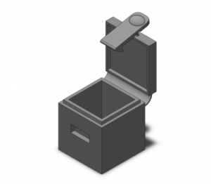
Bennett's example part in isometrics: A simple box with a film hinge and closure flexure.
Alignment of the film hinge
When 3D printing film hinges, the orientation of the part in Eiger is crucial. For greater flexibility, you can use nylon. For a stiffer but more resilient hinge, you can also use Kevlar reinforcement. In both cases, the part must be 3D printed lying on its side. The hinge's bending axis must be perpendicular to the print bed (XY plane).
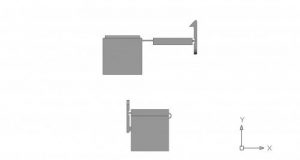
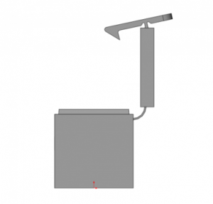
Bennett's box in side view. It's open at the top of the image, and closed below.
There are two reasons why the hinge should be oriented as described. First, reinforcing fiber can only be laid in layers parallel to the XY plane, and it is designed to counteract tensile and bending forces in the longitudinal direction. Second, the tensile strength of nylon within a layer is greater than the adhesive strength between two layers. These two facts play a huge role in the stability of the hinge.
Pay attention to the orientation of the part. For maximum stability, the material properties must be used wisely.
Terminology: Anisotropy
Anyone designing 3D-printed parts needs to understand their anisotropy. Anisotropic material is a material with mechanical properties that often depend on the direction. A great example of this is wood. Many types of wood are easy to separate along their grain. However, they are very difficult to break or cut across it. Isotropic materials, such as many metals, behave in the opposite way. Their properties are much more uniform, regardless of orientation.
Construction of the film hinge
As previously described, the film hinge cross-section is placed on the horizontal Y-plane. The hinge becomes stiffer the more you thicken it. Our example part has a lid hinge and a latch hinge. The lid hinge must be able to move a full 180 degrees. The latch hinge is barely bent but must keep the lid closed. To meet these requirements, the lid hinge is as thin as possible. The latch hinge is thicker and stiffer to prevent the box from opening on its own. The lid is modeled in its neutral position (90 degrees open). The latch hinge is slightly closed to lock into place. 3D-printed flexible parts, much like their injection-molded counterparts, tend to return to their printed state unless they undergo significant plastic deformation. You should take this into account when designing the desired neutral position of your parts.
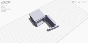
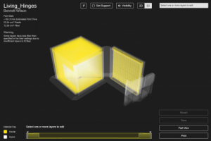
The print-ready part configuration: The lid is at a 90° angle to the box and the snap lock is pre-tensioned.
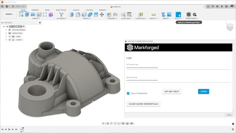
3D printing of the film hinge
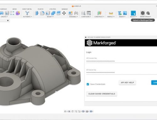
The part is uploaded to Eiger and aligned. Concentric fiber reinforcement is activated for the entire part. The hinges do not meet the required minimum thickness. These areas remain unreinforced. Unlike the Mark One, the Mark Two easily lined the base and lid with fiber. The thin, high walls are also reinforced.
Technical details
- Thickness of the lid hinge: 0.7 mm (maximum flexibility)
- Thickness of the locking hinge: 1.2 mm (stiffer to prevent accidental opening)
- The parts are configured in the open and closed positions to determine the appropriate bend radius. The printing configuration is then selected.
Do you want to 3D print the sample box yourself?
You can download the SWX files here.
You can download the Eiger-ready STL files here.
Check out the Recording of our webinar on bending elements and film hinges to learn more about their construction.
This article was originally published on the Markforged blog. Here go to the original article.
Translated by Antje Kasemann

Learn more about 3D printing with continuous fibers!
Which continuous filament is suitable for which application? How do I design correctly for filament 3D printing? What do users say about it, and where can I find more information? – You've come to the right place! We've listed several information sources that will help you get the answers you need.
Leave A Comment