3D Printing Process
[8 minutes reading time]
FFF 3D printers create parts by extruding layers of material across a layer. The characteristics of each printer – its composition, the quality of its components and its design capabilities – influence the quality and the range of parts it can produce.
Parts of a printer
While FFF printers vary in size, material and function, almost all have three different electromechanical systems. The function of these systems determines your print quality.
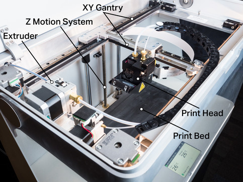
The essential components of a 3D printer, labeled.
Print head and extrusion system: The system that heats and extrudes the thermoplastic printing material through a die to form the part. Factors such as die size and extrusion speed affect the level of detail the printer can achieve and the print speed.
Print bed and Z-movement system: The print head and extrusion system deposits material on the print bed. When printing a part, the Z motion system moves the bed in discrete, equal steps to form the layers of the part. The precision of the motors that drive the Z-motion system controls the resolution and quality of the part as it is built in the Z-direction.
XY portal motion system: The print portal directly controls the X and Y movement of the print head. It is responsible for “drawing” the toolpaths used to create the individual layers. The rigidity of this gantry and the quality of the motors and sensors that control it affect the precision and accuracy of a part in the plane with the print bed.
How is a part built?
An FFF 3D printer builds up its parts in separate levels called layers. As described in our 3D printing software overview, the 3D printing slicer takes an STL file, divides it into layers, calculates them and creates a tool path for each layer. At the beginning of each layer, the print bed is set to a predetermined height and the gantry motion system moves the print head along the toolpath as the extrusion system deposits material.

A 3D printer builds a part by applying the material layer by layer.
The 3D printing process creates a part layer by layer.
Since a 3D printer cannot apply the material in the air, all layers must be bonded at the bottom of the layer. While this applies directly to some parts, others have overhangs that require support. The support structure – or support material – is an automatically generated support framework that comes in various forms:
- Peelable support structure made of the same material as the part,
- soluble support structure, which dissolves in a bath after printing,
- or separation layer support structure, which forms a framework of partial material as an intermediate layer of separation material between the component and the support structure Printers with a secondary material for the support structure use a second nozzle on the printhead specifically for the support structure.
The layer-by-layer principle of the 3D printing process results in 3D printed parts having transverse isotropic material properties. While isotropic materials have uniform material properties in all directions, transverse isotropic materials have one set of properties along an axis and another set on planes perpendicular to that axis. This translates into 3D printed parts that have higher strength on XY planes above the Z axis. Therefore, it is important to consider the print orientation during the design process.

The basics of the filling
While the shell of a part determines the shape and accuracy, the filling in is extremely important for determining the performance. Infill is optimized for strength and print quality and always consists of a tesselating shape distributed over the surface of a plane. Triangles are typically used because of their perfect load distribution, but other shapes can also be used. If you change the shape and density of the filling, the mass and (to a lesser degree) the thickness of your part will change. The orientation of fills depends on the print orientation. So if you want to have an orientation in a particular direction, you must plan for this when you first orient the part.

3D printed parts are usually printed with a sparse fill pattern to save material, cost and printing time.
Continuous fiber reinforcement
Replaces conventional fillings in selected geometries to significantly improve the mechanical properties. At certain layers you can replace the normal filling of a part with automatically guided continuous fibers. The increase in strength that these fibers provide depends on the pressure orientation, how much continuous fiber you add to the part, where continuous fiber is added, and which fiber you want to add.

Endless strands of composite fibres can be applied instead of the filling material, making the part much stronger, stiffer and more durable.
Printing time and material
The printing time depends largely on how many material paths the printer has to draw on each layer. First, the filling prints very fast and the shells are printed very slowly. Second, carriers print very slowly because they have a huge surface area. All these factors add up to the total time needed to print a particular part. As a result, area, carrier and volume are equally important in determining the printing time. Because part volume is difficult to control depending on the size of a part, try to minimize the surface area and supports to reduce printing time.
Printer material estimates are accurate and easy to calculate in 3D printing because a printer knows how much material it will need when extruding a toolpath. Just like calculating the printing time, a similar rule applies to material consumption. The more area and support structure you have, the more material is used. The support structure can account for a significant portion of material consumption. Minimizing the support structure can reduce the material consumption for an equally large part.
3D printing accuracy and size
The accuracy of 3D printing depends on a number of factors, including material, print settings and part orientation. However, there are several ways to increase accuracy:
Printing with default settings: Most industrial printers optimize their printing accuracy using the basic settings.
Print functions that require high accuracy in the XY plane: Since the XY portal is a Unified Motion system, printers on the XY axis (horizontal) produce much more precise geometries than the XZ or YZ axis (vertical). Try to design or align your part so that holes and other important features lie flat on the print bed.
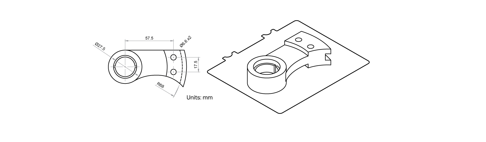
Determine the critical dimensions of your part and align your part so that these features lie flat on the printing bed.
Reduce supports and overhangs: Supports ensure that geometrically complex prints are successful. However, they also affect the supported surface and provide much less accurate features than sections that do not require support.
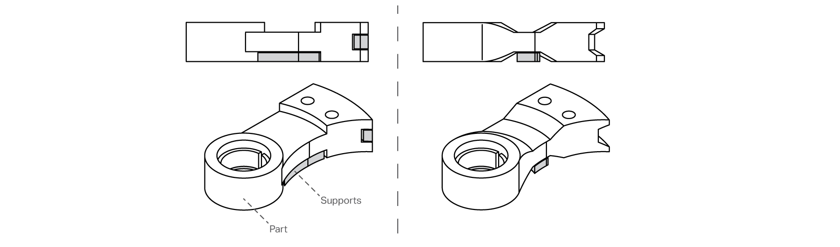
Reducing supports with angled overhangs saves printing time and improves part quality.
Creation volume: The printer size is defined by the creation volume – the maximum range of the gantry and z-motion system. However, this does not mean that you should try to fill the entire volume with a single part. 3D printing is the opposite of subtractive manufacturing, where you start with a block of raw material and try to remove as little material as possible. As a result, large and blocky parts are often cheaper and faster to produce using other methods.
Learn more about the applications with the Desktop Series!
How do I design correctly for filament 3D printing? What do users say and where can I find more information? – This is the right place for you! We listed some information leading you directly to the matching answers.

Economics
If you’re talking about the economics of 3D printing, this guide should help you calculate the ROI of a Markforged 3D printer.
Applications
In this guide we show how you can complement your manufacturing with 3D printed tools. How can you determine a good application? What do you need to consider?

Practical Examples
You can find some case studies and how much cost and time can only be saved by replacing an aid.

AM on the Production-Line
This white paper provides structure and clarity to that task by demonstrating strategies and applications for integrating high strength AM opportunities on the manufacturing floor.