In-house 3D scanning is becoming a core capability for manufacturers looking to reduce downtime, accelerate reverse engineering, and regain control of legacy parts. But beyond the concept, what does in-house 3D scanning actually look like inside a real engineering environment?
Modern manufacturing runs on digital data. Yet in many facilities, critical parts still exist only in physical form – with incomplete drawings, outdated models, or no CAD data at all.
When that part fails or requires modification, engineering teams face a familiar challenge: how do you accurately convert a physical component into usable digital geometry – quickly and reliably?
This is where in-house 3D scanning changes the workflow.
But what does that actually look like in practice?
The Workflow Behind In-House 3D Scanning
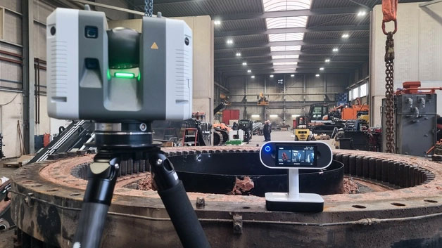
Step 1: Capturing Accurate 3D Geometry
The first stage is data capture.
A handheld professional 3D scanner is used to digitise the physical component directly on-site – whether on the shop floor, in the quality lab, or at an engineering bench.
Unlike manual measurement, scanning captures the complete surface geometry:
- Complex curves
- Internal features
- Worn surfaces
- Intricate detail
- Freeform shapes
Instead of collecting individual dimensions, the system generates a full 3D representation of the part.
For larger components or shop-floor work, portable wireless scanners allow fast capture without complex setup.
For smaller or highly detailed parts, higher-resolution systems can capture fine features with exceptional accuracy.
The result is a high-density mesh file that accurately reflects the physical part. This ability to capture full-surface geometry quickly is what makes in-house 3D scanning practical in busy manufacturing environments.
Step 2: Processing and Cleaning the Scan Data
Raw scan data is processed into a clean, watertight mesh.
At this stage:
- Noise is removed
- Surfaces are aligned
- Multiple scans are merged
- Accuracy is validated
The objective is not just a visual model – but reliable geometry suitable for engineering use.
Modern scanning software allows engineers to see deviations, inspect detail, and ensure the captured data reflects the physical component accurately before moving to CAD.
Step 3: Reverse Engineering into CAD
The mesh data is then imported into reverse engineering or CAD software.
From here, engineers can:
- Reconstruct parametric models
- Extract critical features
- Rebuild geometry with design intent
- Modify worn elements
- Optimise geometry
This is where the workflow shifts from reactive to controlled.
Instead of guessing dimensions from manual measurement, engineering teams are working from accurate, complete digital geometry.
Because in-house 3D scanning provides complete geometry, reverse engineering becomes more predictable and less iterative.
Step 4: Validation and Inspection
Once CAD is rebuilt or modified, scan data can be used for comparison.
This enables:
- Deviation analysis
- Tolerance verification
- Validation against nominal models
- Inspection reporting
For quality and production teams, this accelerates inspection workflows and reduces dependency on traditional measurement bottlenecks.
Step 5: Moving Back into Production
With validated CAD in place, the component can be:
- Re-machined
- Modified
- Manufactured additively
- Documented for future use
The key difference is permanence.
Once digitised, that part no longer disappears into undocumented history. It becomes part of a controlled digital library.
Where This Makes the Biggest Impact
In-house 3D scanning typically delivers the most value when teams are dealing with:
- Legacy tooling
- Obsolete supplier components
- Modified fixtures
- Worn production parts
- Complex geometry difficult to measure manually
It’s not about scanning hundreds of parts per week.
Often, a small number of high-impact components justify the capability.
Does This Require Specialist Metrology Teams?
This is a common concern.
Modern professional scanning systems are designed for engineering environments – not research laboratories. With proper training and defined workflows, engineering teams can integrate scanning into existing CAD and inspection processes without adding unnecessary complexity.
The goal is not to replace every traditional measurement tool. It’s to eliminate bottlenecks where full-surface geometry is required.
From Reactive Fixes to Controlled Digital Workflows
When scanning capability sits inside the organisation, the workflow changes:
Problem occurs – Capture geometry – Rebuild CAD – Validate – Manufacture.
Instead of:
Problem occurs – Measure manually – Outsource – Wait – Rework – Delay.
That shift in control is what makes in-house 3D scanning strategically valuable in modern manufacturing. Instead of reacting to undocumented parts, engineering teams gain a structured, repeatable reverse engineering workflow built on accurate digital data.
Next, we’ll look at how this workflow applies to real legacy components – and how parts move from physical artefact to production-ready CAD in a practical reverse engineering scenario.

Leave A Comment