Fibre Override Sketching – New Eiger Tool

One of the greatest strengths of Markforged technology is the ability to reinforce 3D printed objects with secondary materials, such as fibreglass, carbon fibre and Kevlar. These continuous fibres – as opposed to chopped fibres – give printed objects more rigidity and strength than traditional materials and methods.
Thanks to Eiger, users can make decisions about which fibres to include, where in the part to include them, the infill pattern to use, and the quantity of fibre to use. While there are default settings for fibre inclusion that work well for most applications, having fine control over these settings is a uniquely powerful, and necessary for specialised applications.
Manual fibre overrides have been in place in Eiger for some time, allowing the user to apply fibres to specific layers as needed. Markforged have just announced an expansion to this functionality however; Fibre Override Sketching. With this new feature, it is now possible to specify exactly where in a layer fibre should be applied.
Where is Fibre Override Sketching most useful?
This new feature gives finer control over fibre routing. This means users can use fibres to selectively reinforce key features, without needing to reinforce the entire layer of the object. This allows for greater efficiency, and not to mention cost effectiveness as material usage is reduced.
Within Eiger, the workflow is easy to use. Simply create a fibre override, add your sketch, and the automatic routing will do the rest.

Markforged’s Simulation software works in perfect harmony with this new functionality, too. By simulating the properties of the object with different fibre configurations, you can find the ideal pattern and distribution without needing to print prototypes, ensuring that you get a part with the right strengths the first time.
Example Workflow
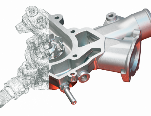
For example, let’s look at the part shown below. This is a fixture for an optical breadboard.
The goal here is to find the ideal print settings, resulting in a finished part that is well within safety tolerances while minimizing material costs. Both are essential, as 250 of these components will be manufactured.

To meet the requirements with a safety factor of 1.5, the part must be able to take a maximum load of 400 N without breaking. This safety factor is in place to guarantee reliability in the real world, and offers security against unforeseen circumstances.
First, the user can use Markforged’s Simulation software to test the performance of the base part without reinforcement, using the profile of Onyx to get control data. The simulation informs the user that the minimum Safety Factory of this object is 1.06 in Onyx, which doesn’t meet the required 1.5.

To improve the object’s strength, the user can add fibreglass in a continuous fibre, using isotropic routing to apply the material on every layer. Applying these settings has a huge effect, nearly tripling the strength with a new Safety Factor of 2.74. This is far stronger than the original design, but the price of this is increased print time and material costs.
With plenty of safety tolerance left over however, the user can reduce the amount of fibreglass used while still meeting their target, cutting material costs significantly. This is where fibre override excels.
Thanks to the new Fibre Override Sketching functionality, fibreglass is only added where it’s needed, and where it is the most effective. In this case, it is the load-bearing part of the object which has the greatest need for strength, between the load and the fastener. After using Fibre Override Sketching, Markforged’s Simulation predicts a Safety Factor of 1.58, meaning the end part still exceeds safety requirements while using significantly less fibreglass.
Compared to the first reinforced part with fibreglass on every layer, the second design optimised by Simulation has a 44% faster print time, and costs 37% less. When printing hundreds of parts, these savings make a huge difference; and in the case of these 250 parts the savings are $1,197 in materials and 34 days of print time.


Summary
The new Fibre Override Sketching functionality in Eiger gives greater control over material placement, enabling material cost savings and complementing the strengths of Markforged’s Simulation software. In combination, these tools make it quick and easy to test iterations of designs, achieving design requirements without using excessive amounts of fibre and time.
All users of Eiger can now access Fibre Override Sketching, and Simulation is available with Advanced Digital Forge Subscriptions.
Get in touch if you would like to learn more, and we’ll be happy to help.
Test the Eiger Software Now!
Request a DEMO Component Now!
Learn more about the applications with the MarkTwo!
Which continuous fibers are suitable for which applications? How do I properly design for filament 3D printing? What do users say about this and where can I find more information? – You are right here! We have listed some information options that will take you straight to the right answers.

Design Guide
This design guide will teach you the best practises for 3D printing with composite materials and fibre reinforcement.
Stronger than Aluminium
For years, a compromise between strength, delivery time and cost had to be accepted. This can now easily be avoided!

Economics of 3D Printing
This white paper illustrates the economics of 3D printing, and how justifying the cost is getting easier every year.

Leave A Comment