Markforged composite filaments, such as carbon fibre, have incredible properties, and can add high strength and stiffness to many 3D printed parts. Like all manufacturing processes, however, composite-reinforced 3D printing is better suited for certain applications which can leverage the advantages of the specific process. In CNC machining operations, for example, a square end mill cutter can produce pocketed features or slots down to a minimum width. This is constrained by the diameter of the end mill selected, so a CNC mill excels at producing pocketed features larger than the minimum size.
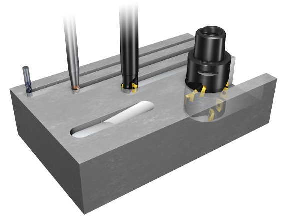
Different diameter cutting tools cutting slots at the minimum possible width for each tool (source: Sandvik Coromant)
Similarly, Markforged composite filaments have a fixed width when printed, and due to spatial limitations, can only be used to reinforce structures which exceed a minimum thickness. A common design challenge our customers encounter when reinforcing a part with composite filaments is that the part has a narrow cross-sectional geometry in a certain region that doesn’t leave room for our composite filaments. Since it’s always more efficient to design a part from the outset with the capabilities of its production process in mind, we’ve come up with this handy guide on best practices for effectively designing parts for composite-reinforced 3D printing.
Reinforce Between the Lines
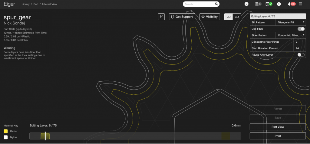
Markforged composite filaments need to be able to flow between the outer nylon shells of a part, so leaving enough space for them is paramount. When reinforcing a thin section, you need to use a concentric fibre ring in Eiger to ensure a single path of fibre is laid down through the narrow geometry. You can do this through using the ‘Concentric Fibre’ fibre pattern in Eiger. Or, if you need additional reinforcement elsewhere in the part, do so by using the ‘Isotropic Fibre’ fibre pattern with at least one ‘Concentric Fibre Ring’ specified. In the image below, I’ve simply used the ‘Concentric Fibre’ pattern to add a single path of Kevlar. Note that specifying a number of ‘Concentric Fibre Rings’ tells Eiger to automatically reinforce the part with up to that number of rings if there is space to do so.
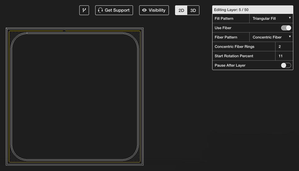
A single path of concentric Kevlar (the yellow path) runs through the thin regions of this part in this cross-section view of the part
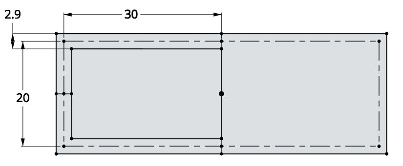
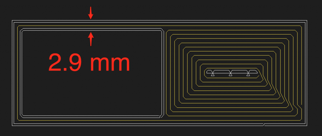
If the cross-section of the part being reinforced allows for a continuous loop (such as in the image above), then a single path of fibre can be laid down to reinforce the part. The width of a fibre path is approximately 1 mm, and with the two nylon shell paths on either side of the fibre, the minimum part thickness that can be reinforced is approximately 2.9 mm. This is the minimum dimension you should incorporate into your design if you wish to reinforce a section with composite fibre.
The minimum width of a part with a continuous loop that can be reinforced with Markforged composite filament is 2.9 mm
The thinnest section of this part is 2.9 mm wide in order to enable the fibre path to be laid down
Turning the Corner
But what about thin sections which project out from the main body of a part and are only connected to the part at one end? This scenario is common in vanes, turbine blades or propellers as an example. In this case, the fibre must double back on itself to make a concentric ring.

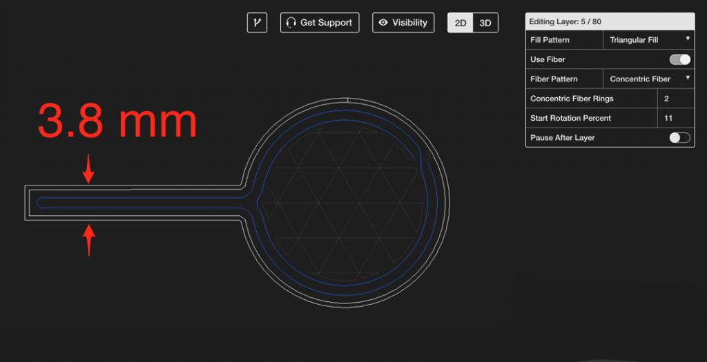
Note the carbon fibre paths shown in blue in this turbine example — the paths leave the rotor hub, loop around the tips of the vanes, and return to the hub
In this case, two paths of fibre need to fit into the projecting feature. As we mentioned before, each path of fibre is approximately 1 mm, which results in a minimum width for a projecting feature of 3.8 mm.
The minimum width of a fibre-reinforced projecting feature is 3.8 mm
The minimum part thickness for a projecting thin feature is 3.8 mm
Further Applications
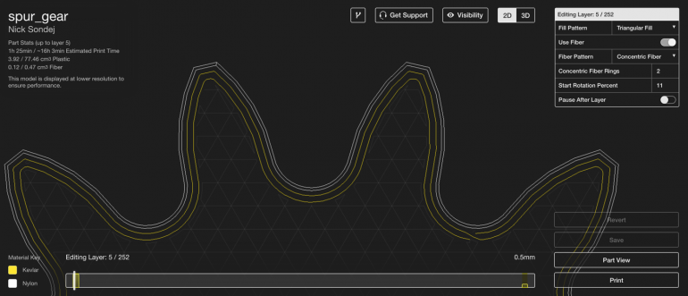
The rule of thumb for projections described above is most important for projecting features which need fibre at critical points along the projection — namely sprockets and gears. In order for the tooth of a gear to be properly reinforced with fibre all the way from the root to the tip, it must be wider than the the minimum 3.8 mm threshold at the tip of the gear tooth.
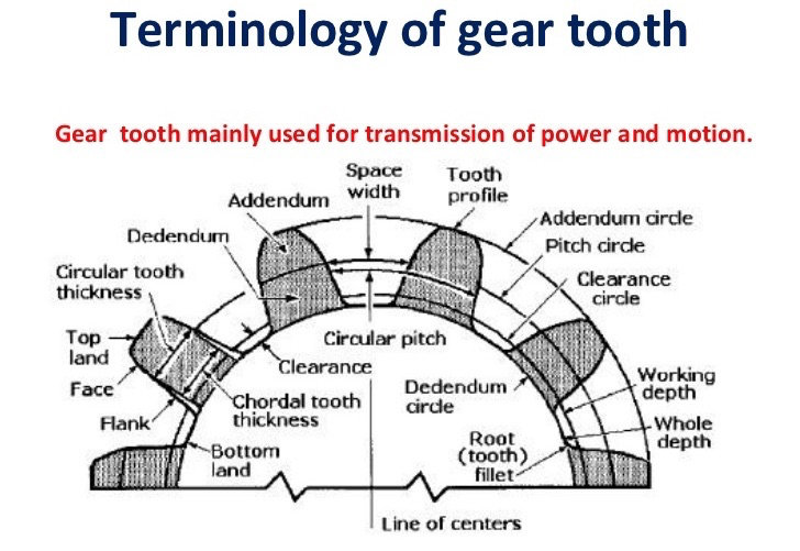
A detailed diagram of the different components of an involute spur gear (source: Slideshare)
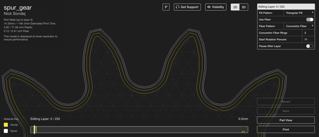
The teeth on this gear are fully reinforced with Kevlar from the root all the way to the tooth tip
In the case of smaller gears and sprockets, fibre can often help reinforce the tooth, but may not be able to fit all the way to the tip. This will still result in a gear that is stronger than a pure plastic one, but may be weaker locally along the tooth than desired.
In this smaller spur gear, fibre reinforcement can only reach slightly beyond the pitch circle of the gear
In summary, to properly reinforce a part with fibre:
- The minimum part width for a thin region connected to a larger part at both ends is 2.9 mm
- The minimum part width for a projecting feature is 3.8 mm
Want to try printing your own industrial strength parts? Request a demo of the Mark Two today!


Leave A Comment