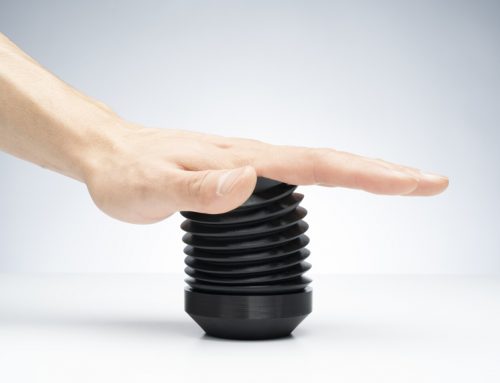
With the launch of Onyx, our new micro-carbon fiber infused nylon filament, we have been excitedly testing what it can achieve. One of our discoveries was that the superior surface finish and dimensional stability of Onyx makes it especially well-suited to creating precise joinery. This inspired us to make a blog covering some guidelines for making robust joinery with a desktop 3D printer.
Joinery is a term usually found in woodworking, referring to the practice of joining two pieces of wood together by geometrically constraining them. Good joinery provides strong connections with little-to-no help from fasteners like nails or screws. Joinery is useful because it ensures a strong connection with a less complicated assembly process. However, it usually involves complicated shapes that take time to design and create, while bolts and screws just require a hole and a mass-manufactured fastener.
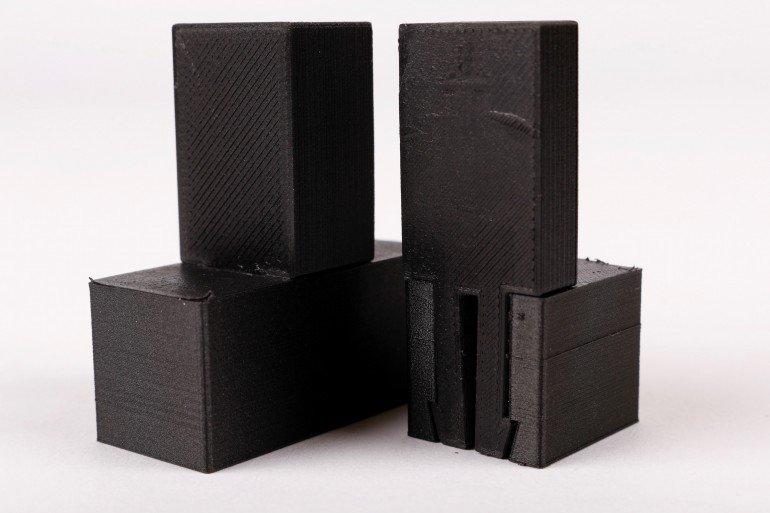
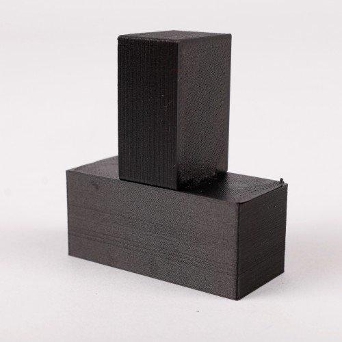
A classic T-bridle joint, printed in Onyx.
3D printing is in an interesting position as a fabrication method because printing complicated geometry is often no more expensive than printing a block. Instead, FDM printing is limited by material properties and the process of building in layers. Thus designing for 3D printing requires a new mindset, and part of that mindset is leveraging the geometric freedom of a 3D printer to reduce the complexity and cost of the final assembly. One way to do that is to look at joinery invented for wood working and injection molding and apply that to the constraints of 3D printing. In this blog, I discuss leveraging simple joints like dovetails and snap fits to improve your printed designs, supplemented by some examples.
Dovetails
A classic dovetail joint.
When it comes to constraining two parts, many people think in right angles. And this is efficient, especially when thinking about machining; right angles are generally much easier and faster to make than odd angles, requiring fewer setups and no special bits or indexing tables. To a 3D printer, however, dovetails and straight walls are all the same. With no extra effort, you can constrain another degree of freedom. This comes in handy everywhere, whether you want a sliding assembly or a fastener-less T-joint.
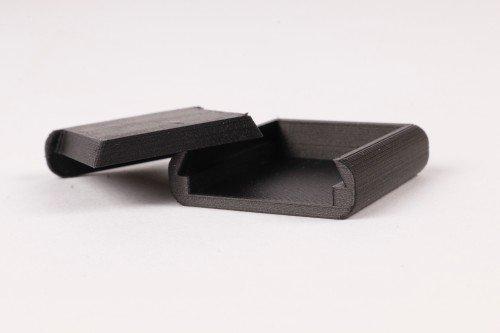
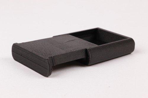
Sliding dovetail box, disassembled.
The flared walls and tight tolerances allow this box to slide smoothly.
When thinking in angles, bear in mind that the established dovetail shape isn’t the only application. The two-part sliding box shown above accomplishes the same restraint as a dovetail, but looks more like a plate with angled sides. This allows it to slide together with the other half of the box easily, and even includes a little detent at the end to snap it shut. This shape would be very hard to manufacture by most other means, but it printed on the Mark Two without support materials and achieved a great fit and surface finish on the first try.
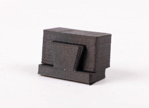
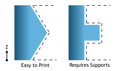
Exploring even further, angled geometry in general can help in 3D printing. For instance, printing a sideways V profile, shown below on the left, can create a constraint that would be difficult to machine, but is trivial to print. Meanwhile, a classic tongue and groove joint, as shown on the right, is hard for most printers to make because of the overhang it creates. This overhang results in a poorly supported bottom face with bad dimensional accuracy, and should be avoided if possible.
Profiles of a sideways V wall (left) and a tongue-and-groove joint (right).
Snap Fits
A commonly used method for cheaply joining injection molded parts is with snap fits. These are good shapes for plastics because they stay within the geometric constraints of mold making and use plastic’s ability to elastically deform and then snap back into shape. Because snap fits are designed for plastic, they are easily adopted for 3D printing…on the XY plane. Most 3D printer users know that objects printed on desktop FDM printers are significantly more susceptible to failure in tension along the Z axis (pointing out of the build plate) than in X and Y, because of the inter-layer boundaries. Since snap fits usually have thin cross-sections (to reduce bending moment of the clip), 3D printed snap fits must be printed “laying down” on the build plate, lest they risk shearing after repeated use.
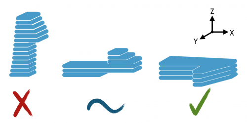
Diagram of cantilever snap joint, printed in three possible orientations.
This diagram shows an exaggerated visualization of the layers of a printed snap fit. When printed upright (pictured at left), the forces that deflect the snap fit also put tension between the layers, making it significantly more likely to break. Printed on its back (pictured at center), a snap fit will definitely be stronger, but still has a shear plane running between the tooth and the arm. Printed laying down on its side (pictured at right), however, the snap fit has no layer boundaries within its cross-section, giving it more predictable strength. And, if the snap fit is big enough, printing it on its side would allow fiber to be routed into the tooth, thereby utilizing the full strength of a Markforged part. This same rule applies for gear teeth, ratchet teeth, and any other protrusion that needs to hold significant load.
Bear in mind also that snap fits can take many forms based on application, and that the design and orientation of the snap fit may change based on your project. In particular, snap fits coming out of 3D printer are not constrained by thicknesses or mold shapes, so you can get creative with where you put them (see below). Printers make it quick and easy to prototype, so try a few geometries before settling on the final shape.
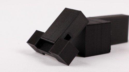
A flush snap fit mortise & tenon joint.
Cross section of flush snap fit mortise & tenon.
Putting it Together: Phone Holder
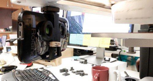
To exhibit sliding fits and snap mechanisms, I designed this cell phone holder that hooks over the hood of the Mark Two and holds any cell phone between 2.5 and 4 inches wide, so that an operator could take a time lapse video or monitor a sensitive print.
The phone holder with a phone in its grasp.
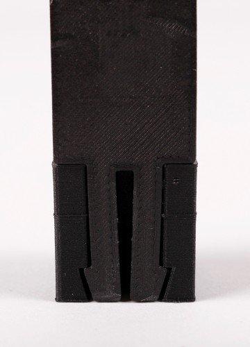
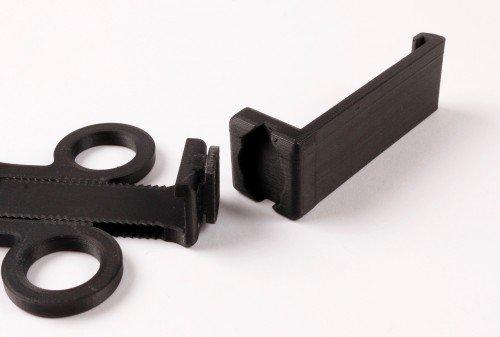
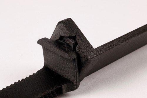
This phone holder has just three parts, two interfaces. One of those interfaces is a twisting joint that acts as a hinge. Though it doesn’t look much like a dovetail, it serves the same purpose: it allows for an easily printable sliding fit, thanks to complementary angles.
Disassembled phone holder (left) and hook (right).
Rotating joint locking into place.
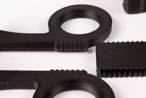
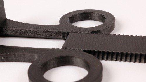
The other interface works like a linear ratchet with angled walls (to keep them from slipping apart) and teeth to set the width of the holder. This would be a very difficult interface to machine make by most other means, but it was quite easy and quick to print!
The teeth of the linear ratchet with the corresponding face (right).
The linear ratchet for adjusting to phone width, engaged.
The phone case in use, watching a Mark Two print.
A Note on Tolerances
As with anything, joinery requires designing in your tolerances. One the Mark Two, for most general purposes, a .08mm gap between each wall (.16mm diametrically) is enough to allow two pieces to consistently achieve a sliding fit. If one of your surfaces is held up by support material, try bumping up the gap to .15mm or so. Of course, 3D printed parts tend to vary widely, so make sure to unit test and prototype to achieve the fit you want.
This is just one small example of how designing with joinery in mind can lead to designs that are simpler and better-fit for your 3D printer. As you find good joints for printing, tweet at us @MarkForged to share your designs and we’ll collect them for a future guide to 3D printed joinery!

