MarkForged Mechanical Features [MMF] is a series of blog posts detailing best practices for designing common traditional engineering parts and mechanical features for composite reinforced 3D printing with MarkForged printers.
Poor vertical part strength is common among FFF (Fused Filament Fabrication) 3D printers especially when loaded in tension. In these 3D printing technologies the bond along the vertical axis is weaker than the strength of the constituent material because in each part there are hundreds of layers adhered to one another along the vertical axis, so the connection between each layer behaves like a seam or a crack when loaded. The in-plane strength of a layer is higher than the inter-layer adhesion because the plastic in each layer is laid down as a continuous extrudate and exhibits the strength properties of the part material itself. On the Mark Two, this directional difference in strengths (or anisotropy) also occurs with our Continuous Filament Fabrication (CFF) process — all of the composite fibers we work with have impressive tensile strength, but because they are laid down along planes parallel to the build plate, that strength is not directly translated into the vertical axis. Proper design for 3D printed parts involves tailoring the geometry of a component such that it will mostly be loaded in the horizontal plane, and parts created by a Markforged printer are no exception. However with some neat design tricks up your sleeve, you can get around this problem and create industrial strength 3D printed parts on the Mark Two with much more isotropic properties.
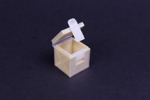
If you’ve handled our materials before, you may have noticed that our nylon can actually be quite flexible by itself. This allows for the design of living hinges, or flexible sections of components that can form a joint or hinge without any assembly required. Learn more about designing living hinges and flexural elements here.
A box printed on the Mark Two with a living hinge for the lid and a flexural element for the latch.
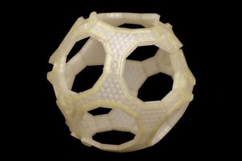
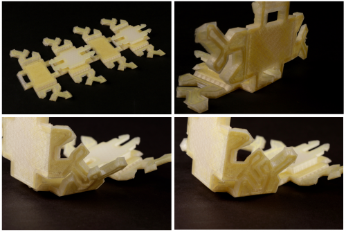
While the fiber reinforcement on the Markforged printer can stiffen up the nylon quite a bit, you can use Kevlar® to create fiber-reinforced living hinges In these folding 3D printed structures, the nylon provides the flexibility, and the fiber provides the joint strength. With a little bit of fiber-reinforced origami, you can design skeletonized parts with minimal support material that are strong in all directions. Here’s an example:
A polyhedron printed on the Mark Two with fiber-reinforced living hinges.
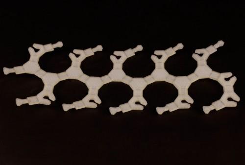
A part like this would have taken an insane amount of time and support material to print as shown, and it would have been pretty weak along the vertical axis, so I designed to print it like this:
To reinforce the part in more directions, this part was printed flat and folded into shape.
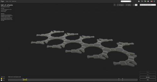
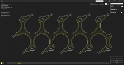
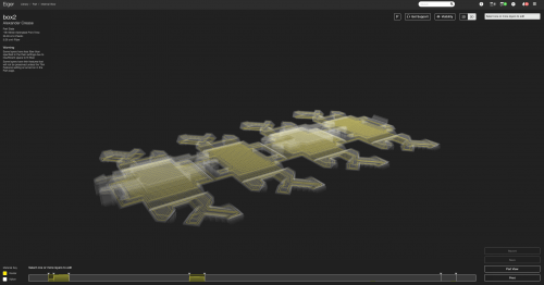
Taking a look at the fiber layout in Eiger, you’ll see only one layer of concentric patterned Kevlar in this print. I chose to use Kevlar because while carbon fiber and fiberglass are stronger, Kevlar is the most flexible of the materials we offer and retains much of its tensile strength even while bent at sharp angles. Carbon fiber and fiberglass are much stiffer and will fracture at bend radii that Kevlar can handle without issue. The single layer of Kevlar provides enough strength for this ball to take on a few dozen pounds, but enough flexibility for the joints to fold nicely.
The Eiger fiber layout for the foldable polyhedron design.
A single layer of Kevlar used to create a fiber-reinforced living hinge.
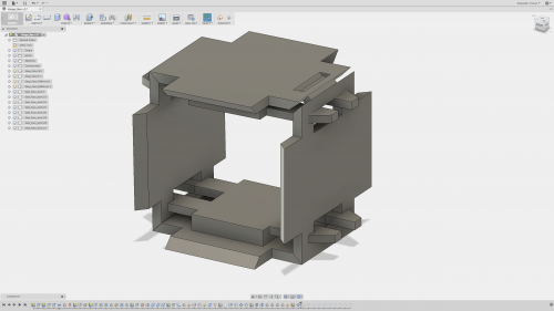
After designing the polyhedron, I upped the stakes to see if I could 3D print something foldable that was strong enough to support my body weight. I decided to keep it simple and designed a foldable Kevlar cube in Autodesk Fusion 360. I needed a method for securing the faces of the cube together, and a joint for connecting faces that weren’t directly adjacent together. I started by modeling four faces of the cube, each as a separate component, so that I could manipulate in the CAD environment to simulate the folding behavior I wanted for my joint. To secure a connection between each face, I designed a snap-fit joint so that when you fold each face into the correct orientation, the face would snap in place and the snap fits would prevent the cube from unfolding or deforming.
The first four faces of the living hinge box.
I also added a small mortise and tenon joint to the edges that would end up connecting once the leftmost face met up with the rightmost.
While most of the edges of the box will be bent, an angled mortise and tenon joint connects the last face together.
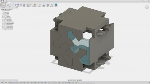
I then decided to try something interesting out with the remaining two sides of the box – on each open remaining edge , I designed a section of each side. Each section has a twist-fit tab and a cut out for the corresponding tab on the adjacent section. Once the box is folded, these can all be snapped together to form the remaining two sides. In the image below, I made one of the pieces transparent to show the chamfers I added to create a dovetail-esque joint that depends on the flexibility of the material to be twisted into place.
The remaining two sides of the folding box are made from a pattern of twist-fit joints.
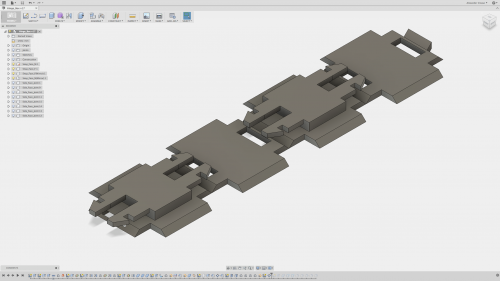
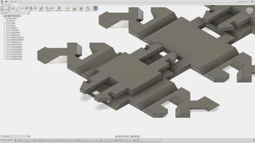
Once the geometries of each face were set in stone, I “unfolded” the cube in CAD so that all the bodies were laid flat in the orientation I wanted the piece printed in. You’ll notice in the image below that each of the components meet along their edges — they aren’t connected yet. At this point, I still needed to combine this into a single, unified part by adding the layers necessary to create the living hinge.
Currently, the parts are only connected on the edges and need to be connected to make the hinge.
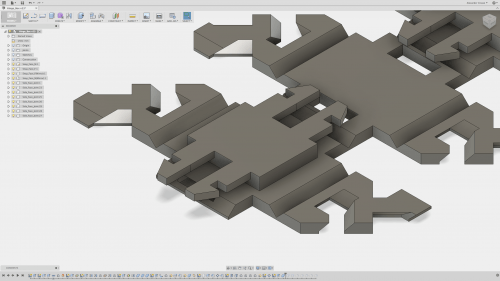
To do this, I captured the profiles of the bottom faces of each component and extruded them out by 0.875 mm, and combined all of the separate bodies into one. This gives thickness to the living hinge: the 0.875 mm thickness adds just enough material for a single layer of Kevlar to fit inside and create a fiber-reinforced living hinge. Notice below that now each edge where the separate components meet now has thickness to it.
The full bottom profile of all the pieces has now been extruded and combined to form joints with thickness.
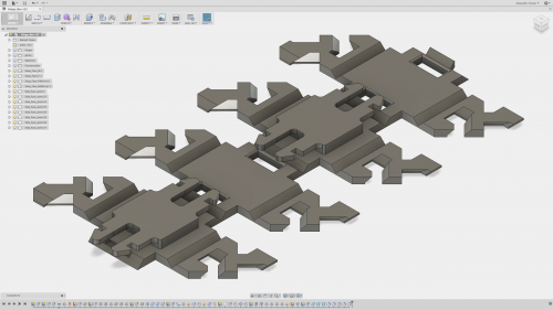
And here’s the full view of the part laid out and ready to print:
The final design for the fiber-reinforced living hinge box.
In Eiger, I laid out concentric rings of fiber on that first Kevlar layer to create and reinforce the joint. To strengthen the rest of the part, I created sandwich panels starting on each face above that first Kevlar layer. As we’ve explained in an older post, sandwich panels are fundamental to composite materials as they provide high strength with low weight. The sandwich panels reinforce each face of the cube to make them strong and stiff 3D printed components – keep in mind each face is only about 3 mm thick. I also was able to fit Kevlar into the snap fit joints to reinforce their small features, which we’ve discussed in a previous post. The GIF below shows the first few layers, including the Kevlar reinforced living hinge layer (layer 5), and the bottom layers of the sandwich panel (layers 6-8).
The first Kevlar layer is concentric and reinforces the living hinges. The next layers are split between the faces of the cube and reinforce each face.
The full Eiger layout of the folding box. Sandwich panels strengthen each side of the box.
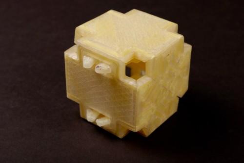
After it printed, I snapped everything together and twisted in the side panel joints, and made a 3D printed foldable cube with some Kevlar reinforcement!
The adjacent faces snap together with snap fits, and the two side faces are comprised of twist-fit joints that lock in place.
The fully assembled fiber-reinforced living hinge box
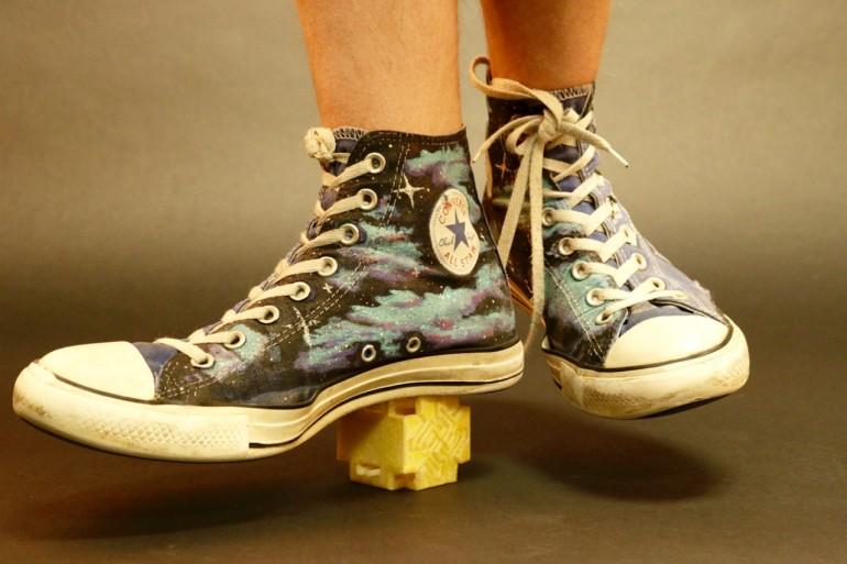
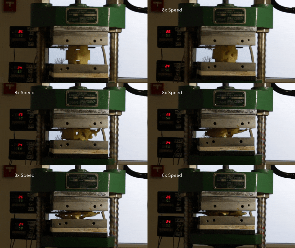
Each side of the cube provides substantial reinforcement in both tension and flexing, making the cube in its entirety very hard to compress and isometric in along the three principal axes. I was able to put my entire body weight on it (about 130 lbs) without even a suggestion of deformation. I’m a fairly small person though, so I did a much more rigorous test. I didn’t get very good readings but I’d estimate it held about 300-400 pounds before failing. Here’s what happened:
The cube being crushed by a small hydraulic press
So after a few hundred pounds, the most surprising thing was that the part didn’t actually break, all of the joints just popped apart and the entire cube flattened, so with a little straightening out it can be brought back to its original form. So by creating foldable structures with fiber reinforced living hinges, you can make some really strong 3D printed parts in all directions.

