
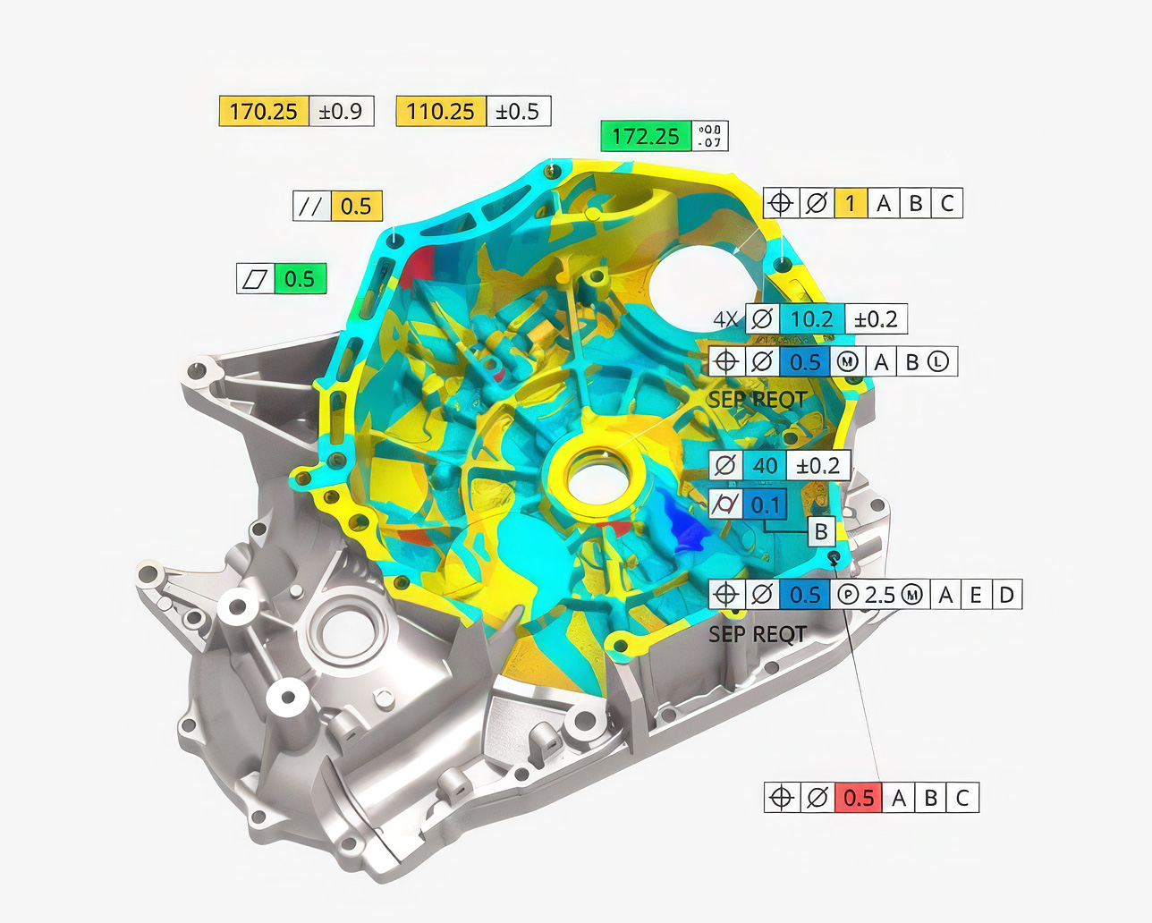
A 3D scan can look impressively detailed and still be unsuitable for dimensional inspection. If the data will be used to approve a component, compare it with CAD or rebuild a critical feature, visual quality is only part of the requirement. The scanning system and the wider workflow must produce measurements that are accurate, repeatable and appropriate for the tolerances that matter.
This is where metrology-grade 3D scanning comes in. It connects fast, non-contact capture with the discipline of measurement, helping manufacturers turn physical components into data they can use with greater confidence for inspection, quality control and reverse engineering.
A detailed model is not necessarily measurement data
Many 3D scanning applications do not require metrology-grade performance. A highly detailed model may be entirely suitable for visualisation, heritage recording, product presentation or creating a starting point for a concept model.
Inspection is different. If the objective is to determine whether a bore is correctly positioned, whether a sealing face is flat enough or whether a manufactured component matches its nominal CAD model, the numerical relationship between the scan and the real part matters. A convincing image is not enough; the data must be fit for the measurement task.
The phrase metrology-grade should therefore mean more than high detail. It should be supported by defined performance specifications, an appropriate test or certification basis and a controlled workflow that considers the scanner, software, operator, component and environment together.
Accuracy and resolution are not the same
Accuracy and resolution are often placed next to each other on a scanner specification sheet, but they describe different characteristics.
Accuracy describes how closely a measured value agrees with the value being measured. In practical 3D scanning terms, it indicates how closely the captured geometry can represent the physical component under the stated conditions.
Resolution describes the scanner’s ability to distinguish small surface details. Higher resolution can reveal sharper edges, fine textures and smaller geometric features.
A scan can therefore contain a dense, visually smooth surface without every point being positioned accurately enough for inspection. Equally, a scanner may offer excellent measurement accuracy but still need the right resolution to capture the feature being assessed. The application normally requires an appropriate balance of both.
Why volumetric accuracy matters
A point-accuracy figure is useful, but it does not always describe how performance behaves across a larger component or measurement volume. As the distance between measured features increases, additional effects can influence the relationship between different areas of the scan.
Volumetric accuracy expresses performance across a defined distance or volume. This becomes increasingly important when scanning larger parts, assemblies or features that sit far apart. A scanner that is well suited to a small component is not automatically the right choice for a long mould tool, vehicle panel or large fabricated structure.
When comparing systems, look at the complete specification and the conditions attached to it. Ask what size of object was considered, how the result was validated and whether the quoted performance matches the scale and tolerance of your own application.
Repeatability certification and traceability
Inspection is rarely based on a single impressive result. A useful measurement process should produce consistent results when the same part is captured again under comparable conditions. This is why repeatability matters alongside headline accuracy.
Certification or testing against recognised standards gives customers a clearer basis for understanding how performance has been evaluated. It does not remove the need for a controlled process, but it is more meaningful than an accuracy figure presented without an explanation of the method behind it.
Traceability is a property of the measurement process, not simply a label attached to the scanner. Calibration status, reference artefacts, software settings, environmental control, operating procedures and reporting requirements may all contribute. For formal inspection work, these elements should be defined before scanning begins.
The component and environment influence the result
Scanner selection is only one part of a reliable workflow. The physical component and the conditions in which it is scanned can have a significant effect on data capture.
- Component size and tolerances: The overall size of the part and the smallest critical tolerance help determine the required accuracy, resolution and measurement volume.
- Surface condition: Dark, polished, reflective or transparent surfaces can be more challenging for optical systems. The scanner technology, capture mode and any permitted surface preparation need to be considered.
- Access and geometry: Deep recesses, tight assemblies, sharp edges and confined spaces may affect line of sight and the number of passes required.
- Temperature and stability: Components and measurement systems can change as temperatures vary. Vibration, movement and unstable fixtures can also affect the workflow.
- Tracking and alignment: The method used to maintain position across the scan, including geometry, texture, targets or other references, should suit the required accuracy and the component being captured.
- Operator and process: Planning the scan path, maintaining the correct working distance and applying consistent processing settings all contribute to the quality of the final result.
Full part metrology and tolerance driven scanning
Not every inspection or reverse engineering task needs the same level of measurement control across every surface.
Some applications require metrology-grade performance across the complete part. This may be appropriate when many features interact, the whole surface must be compared with CAD or the inspection plan demands consistent control throughout the dataset.
In other cases, only particular features determine whether the component will fit or function correctly. Bores, mounting points, datums, sealing faces and alignment features may carry tight tolerances, while surrounding freeform surfaces require complete geometry but not the same level of measurement control.
Tolerance-driven scanning applies metrology where design intent demands it, while still capturing the complete component. This can make the workflow more efficient without treating non-critical areas as though they carry the same tolerances. Read our introduction to tolerance-driven 3D scanning to explore this approach in more detail.
Start with the required output
The most productive scanner conversations begin with the result, not the product. Before comparing specifications, define what the captured data must allow you to do.
- Is the goal visualisation, reverse engineering, dimensional inspection or formal quality reporting?
- Which features determine whether the component will fit or function?
- What are the relevant tolerances, and where do they apply?
- How large is the component and how far apart are the critical features?
- Does the component have reflective, dark, delicate or difficult-to-access surfaces?
- Will the data need to integrate with CAD, inspection or reporting software?
- What evidence, repeatability or traceability does the organisation require?
These questions provide a much stronger basis for selecting a scanner than choosing the system with the smallest number on a specification sheet.
Matching the scanning approach to the application
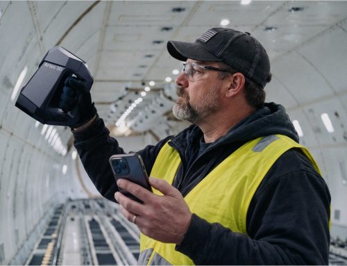
Different metrology-capable scanners solve different problems. A portable laser scanner may be well suited to reflective industrial components, confined spaces and target-based measurement. A hybrid optical system may offer a more flexible balance between metrology around critical features and high-resolution capture across the rest of the part. Automated desktop scanning can be appropriate for smaller components where repeatable positioning and minimal operator input are priorities.
The right choice depends on the complete application: part size, tolerances, surfaces, access, working environment, software requirements and the experience of the people who will use the system. In some cases, a scanning demonstration against a representative component is the most useful way to verify the workflow before making a decision.
How Mark3D can help
Mark3D supports customers in evaluating professional 3D scanning for inspection, reverse engineering and digital capture. We begin with the component, the required output and the tolerances that matter, then recommend an appropriate scanner, software workflow and demonstration.
If you have a component or measurement challenge in mind, bring it to our team. We can help you determine what level of accuracy and detail the application requires and demonstrate how the proposed workflow performs against a relevant part.


Leave A Comment